00194103-01.pdf - 第70页
3 Technical data User Manual S IPLACE F5 H M 3.1 Description of t he machine Software Vers ion SR.408.xx 03/2006 US Edition 70 The placeme nt heads pi ck up com ponents from stationa ry feeders and use them to populate t…
User Manual SIPLACE F5 HM 3 Technical data
Software Version SR.408.xx 03/2006 US Edition 3.1 Description of the machine
69
3 Technical data
3.1 Description of the machine
The placement machine is a high-performance placement system with one gantry. It holds a 6/
12-segment Collect&Place head, a Pick&Place head and a PCB camera.
3
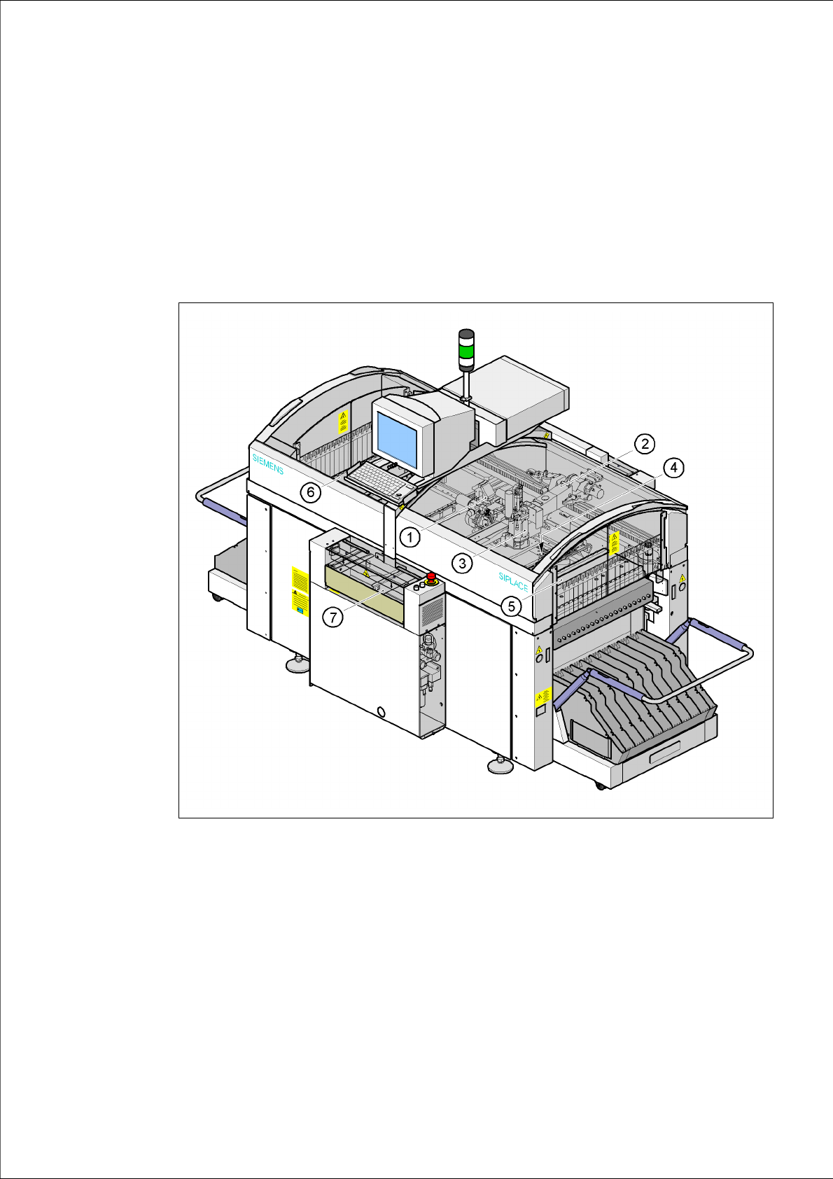
Fig. 3.1 - 1 Overall view of the placement system
(1) 6/12-segment Collect&Place head with component camera
(2) Gantry 1 with PCB camera
(3) Pick&Place head
(4) Fine-pitch vision camera for the Pick&Place head
(5) Stationary component supply (location 1)
(6) Stationary component supply (location 3)
(7) PCB conveyor (dual conveyor option)
3 Technical data User Manual SIPLACE F5 HM
3.1 Description of the machine Software Version SR.408.xx 03/2006 US Edition
70
The placement heads pick up components from stationary feeders and use them to populate the
PCB clamped on the PCB conveyor.
The 12-segment Collect&Place head can process size 0201 to 18.7 mm x 18.7 mm components.
The 6-segment Collect&Place head can raise the placement rate when there is a high proportion
of ICs in the placement process. The component sizes range from 0603 to 32 x 32 mm². Even
smaller components can be placed such as 0201 when using the DCA and 0201 packages.
The Pick&Place head is particularly suitable for placing fine pitch components. It places compo-
nent sizes ranging from 1.6 x 0.8 mm² to 55 x 55 mm². In addition to the PCB centering vision
module, the placement machine also has component vision modules for the Collect&Place head
and Pick&Place head.
The concept behind the automatic placement system
– with its stationary feeders,
– PCBs that do not move during placement
– and positionable placement heads
has a number of significant benefits:
– For example, the flexible 6/12-segment Collect&Place heads combined with automatic nozzle
changer enables the nozzle configuration to be changed temporarily and automatically
adapted to receive different component sizes. The same applies to the Pick&Place head. You
can also optimize the traversing paths and the placement sequence.
– With stationary feeders, even the tiniest components are picked up reliably.
– The components cannot slip on the PCB during placement (as is often the case with moving
PCBs) since the PCB does not move.
– Sophisticated optical centering systems (vision modules) for components and PCBs also en-
sure high component positioning accuracy.
– Components can be topped up and tapes can be spliced without stopping the machine.
– Prepared component trolleys enable the placement system to be retooled without long stop-
pages.
A waffle-pack changer may be used to supply components.
User Manual SIPLACE F5 HM 3 Technical data
Software Version SR.408.xx 03/2006 US Edition 3.1 Description of the machine
71
3.1.0.1 Head modularity concept (Head Modularity)
The abbreviation HM in the designation of the SIPLACE F5HM placement system stands for
Head Modularity. 3
Changing from a 6-segment to a 12-segment Collect&Place head and vice versa will enable the
system to be quickly adapted to the requirements of individual placement jobs. 3
3
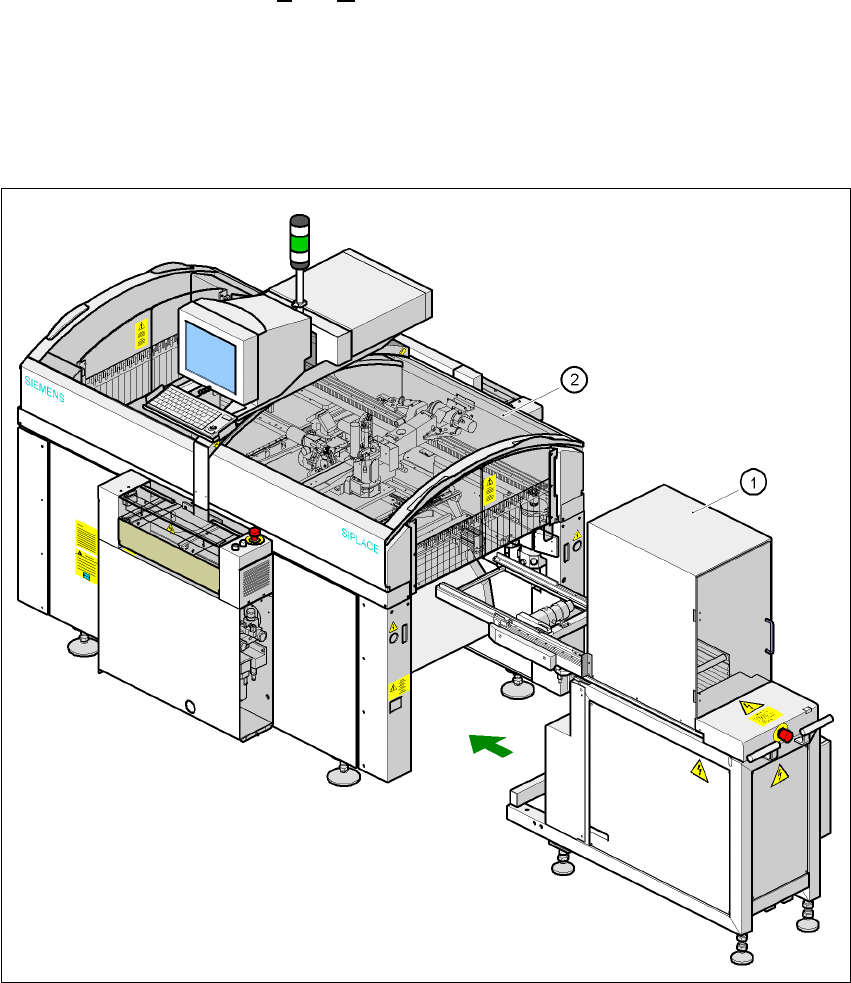
Fig. 3.1 - 2 SIPLACE F5 HM overall view with waffle-pack changer
(1) Waffle-pack changer
(2) SIPLACE F5 HM