00194103-01.pdf - 第49页
User Manual SIPLAC E F5 HM 2 Operational safety Software Vers ion SR.408.xx 03/2006 U S Edition 2.5 Safety equipment 49 2.5 Safet y equipme nt 2.5.1 Protectiv e cover s 2 Fig. 2.5 - 1 Safety equipment in the placement ma…
2 Operational safety User Manual SIPLACE F5 HM
2.4 Safety instructions for operating the machine Software Version SR.408.xx 03/2006 US Edition
48
The feeder modules are labeled as shown below:
2
WARNING FIRE HAZARD 2
Æ Check and empty the waste tape container every hour.
Æ Only empty the waste tape container into suitable collection containers because of the risk of
fire. These containers must not be set up inside buildings.
User Manual SIPLACE F5 HM 2 Operational safety
Software Version SR.408.xx 03/2006 US Edition 2.5 Safety equipment
49
2.5 Safety equipment
2.5.1 Protective covers
2
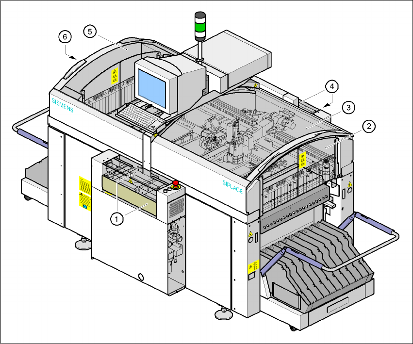
Fig. 2.5 - 1 Safety equipment in the placement machine
(1) Cover and guard on the input belt
(2) Safety panels, right-hand side
(3) Protective cover
(4) Cover and guard on the output conveyor
(5) Protective cover
(6) Safety panels, left-hand side
2 Operational safety User Manual SIPLACE F5 HM
2.5 Safety equipment Software Version SR.408.xx 03/2006 US Edition
50
2.5.1.1 General
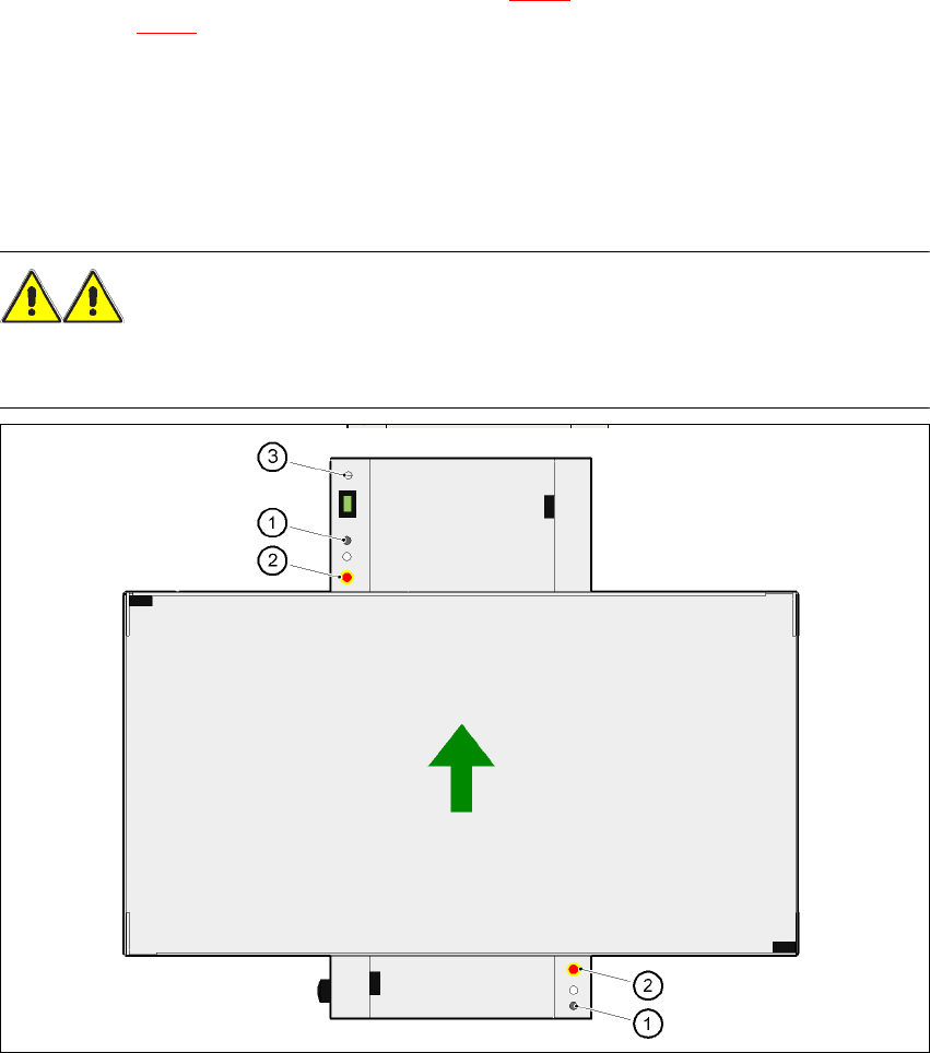
The gantry positioning range is covered by two protective covers. If you want to open the protec-
tive covers, first press the Stop button (item 1 in Fig. 2.5 - 2
) or the EMERGENCY STOP button
(item 2 in Fig. 2.5 - 2
). The power to the gantry axes will be switched off and the gantries will stop
immediately. If you open one of the protective covers or a guard on the incoming or outgoing con-
veyor, the power to the gantry axes will be switched off. They will stop immediately. 2
Placement will stop if you press the EMERGENCY STOP button. You can then either cancel or
continue placement of the PCB. The protective covers at the sides can be opened in order to refill
with components when the machine has stopped. 2
WARNING
The protective covers must only be opened, with the key switch closed (position I), by appropri-
ately qualified and trained personnel. 2
Fig. 2.5 - 2 Stop button and EMERGENCY STOP button, key switch
(1) Stop button
(2) EMERGENCY STOP button
(3) Key-operated switch