00194103-01.pdf - 第74页
3 Technical data User Manual S IPLACE F5 H M 3.4 Electrical and pneumat ic connection points Software Vers ion SR.408.xx 03/2006 US Edition 74 3.4 Electrical and pneuma tic connection point s 3 Fig. 3.4 - 1 Electrical an…

User Manual SIPLACE F5 HM 3 Technical data
Software Version SR.408.xx 03/2006 US Edition 3.3 The line concept
73
3.3 The line concept
3.3.1 Overview
The placement system can be linked to input and output stations, screen printing systems, sol-
dering ovens and other automatic placement systems from the SIPLACE CS, CF and the S-23
range. All SIPLACE modules are provided with the necessary data by the SIPLACE Pro com-
puter as appropriate. The placement system can also be linked to a higher level data processing
system through the use of suitable interfaces. 3
3.3.2 Technical data – line concept
3
3
3
System SIPLACE placement lines
Modules SIPLACE CS / SIPLACE CF / SIPLACE S-23 /
SIPLACE F5 HM
Peripherals Input/output stations
Screen printers
Soldering ovens
Inspection stations, etc.
Component range from 0201 to 55 x 55 mm²
PCB conveyor Automatic width adjustment
PCB format 50 x 50 mm² to 460 x 460 mm²
Placement rate Depends how modules are connected in series
Space required 4 m² / module
3 Technical data User Manual SIPLACE F5 HM
3.4 Electrical and pneumatic connection points Software Version SR.408.xx 03/2006 US Edition
74
3.4 Electrical and pneumatic connection points
3
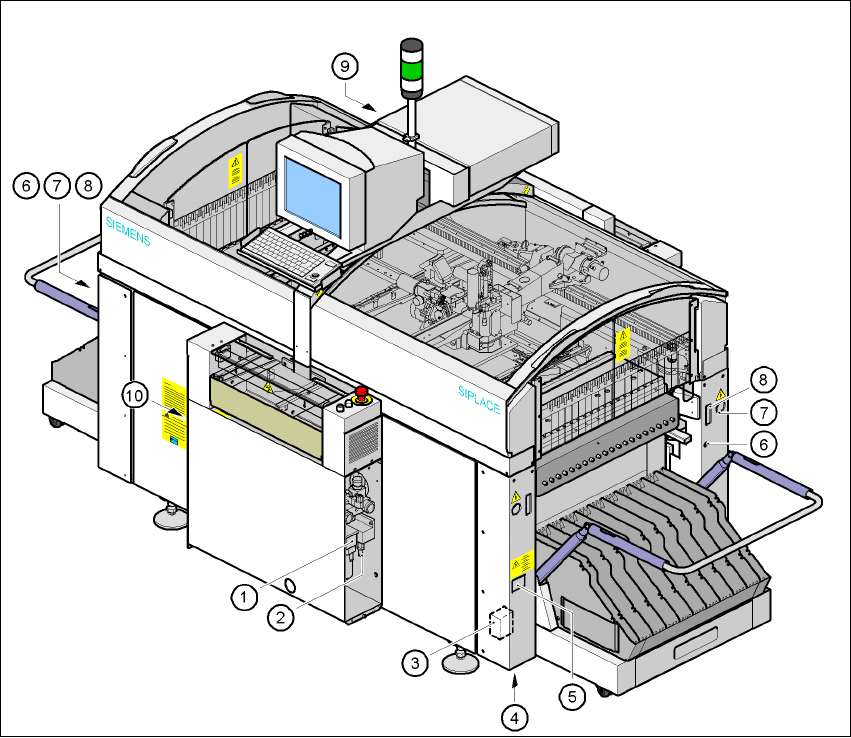
Fig. 3.4 - 1 Electrical and pneumatic connection points on the machine
(1) Compressed air unit
(2) Connection for compressed air line
(3) Main power filter Z1
(4) Hole for power cable
(5) Service socket
(6) Compressed air connection for component trolley
(7) Power connection for the component trolley
(8) Communications connection for the component trolley
(9) LAN connection in the control unit
(10) Main power switch
User Manual SIPLACE F5 HM 3 Technical data
Software Version SR.408.xx 03/2006 US Edition 3.4 Electrical and pneumatic connection points
75
DANGER
The placement system is supplied with 3 x 400 VAC or 3 x 208 VAC US version) ± 5%, 50/60 Hz
main power voltage. This means that some parts of the system carry potentially lethal voltages
- even when switched off at the main power switch. Death, serious injury or considerable damage
may result if this automatic placement system is handled incorrectly. 3
WARNING
Never disconnect compressed air lines while they are pressurized. Risk of injury. 3