00194103-01.pdf - 第92页
3 Technical data User Manual S IPLACE F5 H M 3.9 Placement heads Software Version SR.408.xx 03/2006 US Edition 92 3.9.7 St ructure of the Pick &Place head 3 Fig. 3.9 - 3 Structure of the Pick&Place head (1) Sleev…

User Manual SIPLACE F5 HM 3 Technical data
Software Version SR.408.xx 03/2006 US Edition 3.9 Placement heads
91
3.9.5 Description of the 6-segment Collect&Place head
The functionality of the 6-segment revolver head is similar to that of the 12-segment revolver
head. With its standard vision module, the 6-segment Collect&Place head can quickly and accu-
rately place ICs with an edge length of up to 32 x 32 mm². It really comes into its own when there
is a very high proportion of ICs in the placement process. The cycle time of the 6-segment Col-
lect&Place head depends on the dimensions and number of component leads or bumps. 3
3.9.6 Technical data for the 6-segment Collect&Place head with
standard component vision module
3
Range of components 0603 to 32 x 32 mm²
Max. height 8.5 mm
Min. lead pitch 0.5 mm
Min. bump pitch 0.56 mm
Min. ball/bump diameter 0.32 mm
Min. dimensions 1.6 x 0.8 mm²
Max. dimensions 32 x 32 mm²
Max. weight 5 g
Programmable set-down force 2.4 to 5.0 N
Placement rate 8,500 comp/h
Nozzle types 8 xx, 9 xx
Angular accuracy ± 0.225° / 3 σ, ± 0.30° / 4 σ, ± 0.45° / 6 σ
Placement accuracy with standard vision
module
± 52.5 µm / 3 σ, ± 70 µm / 4 σ, ± 105 µm / 6 σ
3 Technical data User Manual SIPLACE F5 HM
3.9 Placement heads Software Version SR.408.xx 03/2006 US Edition
92
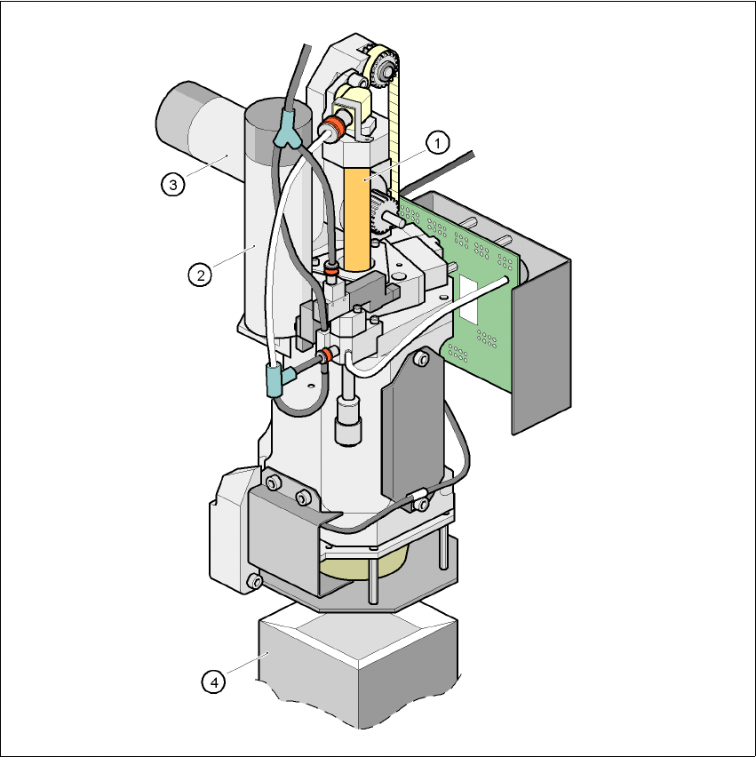
3.9.7 Structure of the Pick&Place head
3
Fig. 3.9 - 3 Structure of the Pick&Place head
(1) Sleeve
(2) DR axis drive
(3) Z axis drive
(4) Fine-pitch vision module

User Manual SIPLACE F5 HM 3 Technical data
Software Version SR.408.xx 03/2006 US Edition 3.9 Placement heads
93
3.9.8 Description of the Pick&Place head
The Pick & Place head works on the Pick&Place principle. According to this principle, a compo-
nent is picked up by the nozzle with the aid of a vacuum. It is then optically centered by the fine-
pitch or flip-chip vision module, turned in the placement angle and placed on the PCB with high
precision. The Pick&Place head offers particularly high angular accuracy. 3
3.9.9 Technical data - Pick&Place head
3
Range of components 1.6 x 0.8 mm² up to 55 x 55 mm² (fine-pitch vision module)
1.0 x 1.0 mm² up to 20 x 20 mm² (flip-chip vision module)
Max. height Component height ≤ 13.5mm- PCB thickness
- PCB warpage
Option:
Component height ≤ 20mm- PCB thickness
- PCB warpage
Min. lead pitch 0.4 mm (fine-pitch vision module)
0.25 mm (flip-chip vision module)
Min. bump pitch 0.56 mm (fine-pitch vision module)
0.14 mm (flip-chip vision module)
Min. ball/bump diameter 0.32 mm (fine-pitch vision module)
0.08 mm (flip-chip vision module)
Max. dimensions up to 32 x 32 mm² with single measurement
up to 55 x 55 mm² with quadruple measurement
Max. weight 25 g
Programmable set-down force 1 - 10 N
Nozzle types 4xx, 5 standard nozzles and flip-chip nozzle with nozzle changer
Component centering Fine-pitch vision module (standard)
Flip-chip vision module, option (see Section 7.8
, page 202)
Placement rate 1,800 comp/h
D axis resolution 0.005°
Angular accuracy ± 0.053° / 3 σ, ± 0.07° / 4 σ, ± 0.105° / 6 σ
Placement accuracy Fine-pitch vision module:
± 37.5 µm / 3 σ, ± 50 µm / 4 σ, ± 75 µm / 6 σ
Flip-chip vision module:
± 30.0 µm / 3 σ, ± 40 µm / 4 σ, ± 60 µm / 6 σ