00194103-01.pdf - 第202页
7 Options User Manual SIP LACE F5 HM 7.8 Flip-chip vision m odule for the Pick &Place head Software Version SR .408.xx 03/2006 US E dition 202 7.8 Flip-chip vision module for the Pick&Place head Fig. 7.8 - 1 Visi…
User Manual SIPLACE F5 HM 7 Options
Software Version SR.408.xx 03/2006 US Edition 7.7 Nozzle changer for the Pick&Place head
201
– There is a positioning fiducial for position detection on each magazine of the nozzle changer
(item 1
in Fig. 7.7 - 2
).
– The individual locations are numbered consecutively from 1 to 4.
– The individual nozzle garages in the individual magazines are numbered consecutively from 1
to 5.
– The nozzles are fixed in position in the holder using sprung hooks. The nozzles are either
clamped or released according to the direction of rotation of the Pick&Place head axis.
7.7.4 Notes on operation and maintenance
Æ
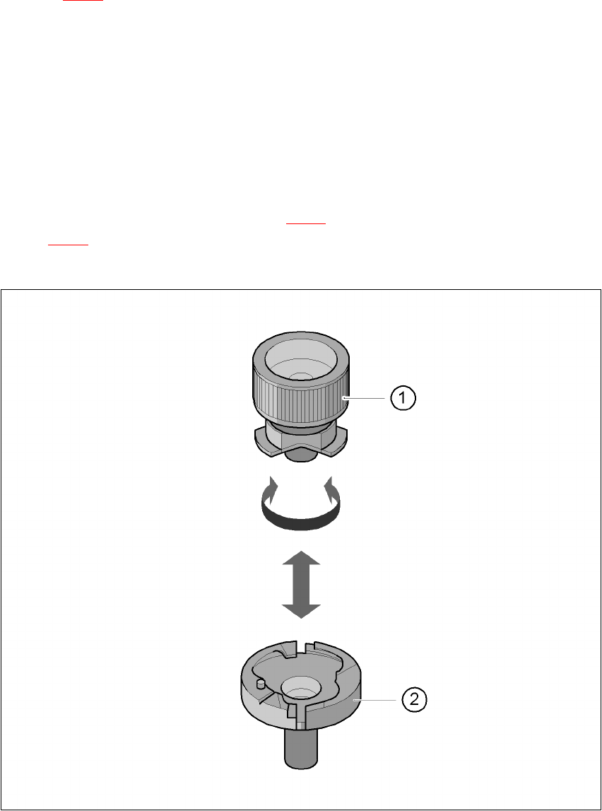
Use the nozzle removal tool (item 1 in Fig. 7.7 - 3) to insert and change the nozzles (item 2 in
Fig. 7.7 - 3
).
Æ Clean the nozzle changer as described in the preventive maintenance instructions.
7
Fig. 7.7 - 3 Remove nozzle from the nozzle changer
7 Options User Manual SIPLACE F5 HM
7.8 Flip-chip vision module for the Pick&Place head Software Version SR.408.xx 03/2006 US Edition
202
7.8 Flip-chip vision module for the Pick&Place head
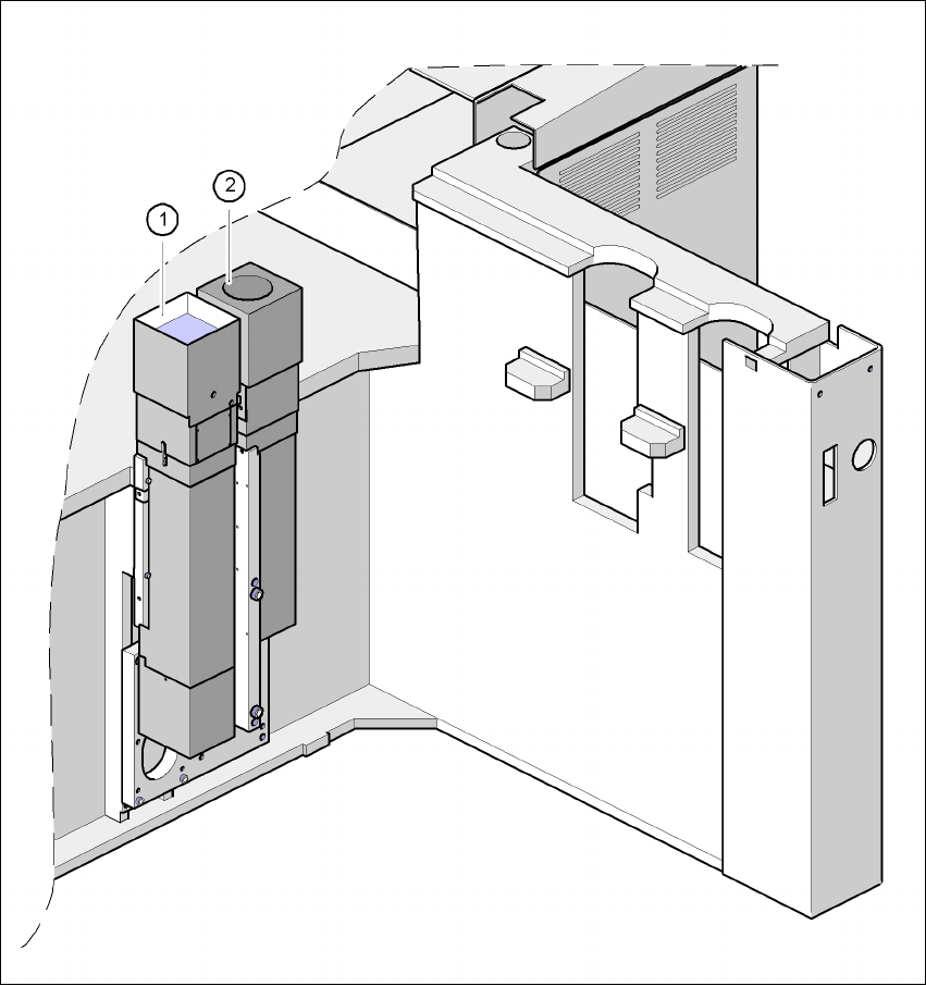
Fig. 7.8 - 1 Vision module for the Pick&Place head
(1) Fine-pitch vision module for the Pick&Place head
(2) Flip-chip vision module for the Pick&Place head

User Manual SIPLACE F5 HM 7 Options
Software Version SR.408.xx 03/2006 US Edition 7.8 Flip-chip vision module for the Pick&Place head
203
7.8.1 Description of the functions
The flip-chip vision module increases the capability for processing fine-pitch and flip-chip compo-
nents with extremely fine lead pitches. This add-on module for the fine-pitch vision module
increases the resolution many times. The lighting layout is fundamentally different. At optimal illu-
mination, the images of bumps are as large as possible, and disruptive orthogonal structures (as
can occur on chip printed conductor tracks, for example) are suppressed. With less pronounced
disruptive structures, enhanced illumination intensity can be achieved by combining lighting fix-
tures resulting in high recognition reliability, even with the generally square connection surfaces
of ‘bumped’ flip-chips as used in conductive adhesive technology. Special search algorithms are
used to recognize the bumps in environments subject to disruption.
7.8.2 Technical data
Flip-chip size
with single measurement
with multiple measurement
1 x 1 mm²
up to 7 x 9 mm²
up to 20 x 20 mm²
Dimensions < 3mmx6mm Special nozzle, feeding tolerance < 0.2 mm edge
length
Min. bump diameter 80µm
Placement cycle minimum 2 sec (depending on the number of bumps)
IC pitch:
Lead pitch
Bump pitch
0.25 mm
0.15 mm
Field of vision 9 x 11.5 mm²
Method of illumination Front lighting (three levels, programmable as
required)