00194103-01.pdf - 第207页
User Manual SIPLAC E F5 HM 7 Options Software Version SR.408.xx 03/ 2006 US Edition 7.9 Coplanarity laser module 207 7.9. 4 Ove rview 7.9.4.1 Analysis uni t The cop lanarit y laser mo dule cons ists of two com ponents: t…
7 Options User Manual SIPLACE F5 HM
7.9 Coplanarity laser module Software Version SR.408.xx 03/2006 US Edition
206
7.9.3 Safety instructions
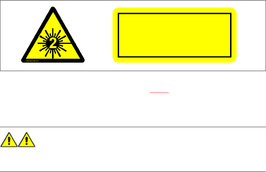
The sensor works with a semiconductor laser of wave length 670 nm (visible/red).
The maximum optical output is £ 1 mW.
The sensor is classified as laser class 2.
– When operating the sensor, always follow the relevant regulations of VDE 0837 concerning
"Radiation safety for laser equipment" and German accident prevention regulation entitled
"Laser radiation" (VBG 93).
– Also follow the accident prevention regulations applicable in your country.
As a precautionary measure, an audible or visual warning should be emitted to signal that the la-
ser is in use.
The following information plates are attached to the front and back of the sensor housing:
7
Fig. 7.9 - 2 Identification of laser class 2 for the sensor
The working laser is signaled by an LED (see Section 7.9.4.2).
NEVER look directly into the laser beam, despite the low laser output. The beam is visible, so the
eyes will be protected by the natural eyelid-closing reflex.
WARNING 7
Only authorized personnel may open the housing of the optical sensor.
For repair and servicing, always return the sensors to SIEMENS A&D.
7
7
LASER RADIATION
DO NOT LOOK INTO BEAM
LASER CLASS 2 PRODUCT
P ≤ 1 mW λ = 670 nm

User Manual SIPLACE F5 HM 7 Options
Software Version SR.408.xx 03/2006 US Edition 7.9 Coplanarity laser module
207
7.9.4 Overview
7.9.4.1 Analysis unit
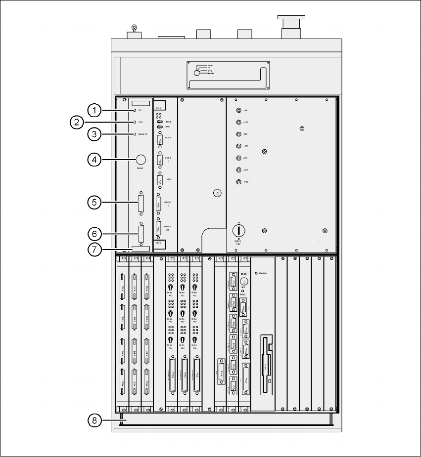
The coplanarity laser module consists of two components: the analysis unit with its control sec-
tion, and the laser module. The analysis unit is located in the control unit (see Fig. 7.9 - 3
). The
operating state is indicated by three green LEDs on the front panel of the analysis unit:
Press the RESET key to initialize the coplanarity laser module.
7.9.4.2 Laser module
The laser module is fixed to a supporting frame on the right-hand side of the machine (see Fig.
7.9 - 4
). Two red LEDs and one green LED signal the operating states of the laser module:
LED (see 7.9 - 3
) On Off
1 green 5 operating voltage No voltage
2 green 12V operating voltage No voltage
3 green Laser module in use Laser module switched off
LED (see Fig. 7.9 - 4) On Off
4 red OUT OF RANGE
(outside the measuring range)
–
5 red POOR TARGET
(component is insufficiently reflec-
tive)
–
6 green Laser module in use Laser module switched off
7 Options User Manual SIPLACE F5 HM
7.9 Coplanarity laser module Software Version SR.408.xx 03/2006 US Edition
208
Fig. 7.9 - 3 Coplanarity laser module - Analysis unit
(1) Green LED: 5V operating voltage
(2) Green LED: 12V operating voltage
(3) Green LED: laser module switched on
(4) RESET key
(5) SUB-D plug, 9-pin, COM2: to the machine controller
(6) SUB-D plug, 15-pin: to the laser module
(7) Analysis unit with control section
(8) Control unit