00194103-01.pdf - 第99页
User Manual SIPLAC E F5 HM 3 Technical data Software Version SR.408.xx 03/ 2006 US Edition 3.12 PCB dual conveyor 99 There are two conv eyor mode s: Dual conv eyor synchr onous and "Du al conveyor asy nchronous &quo…
3 Technical data User Manual SIPLACE F5 HM
3.12 PCB dual conveyor Software Version SR.408.xx 03/2006 US Edition
98
3.12 PCB dual conveyor
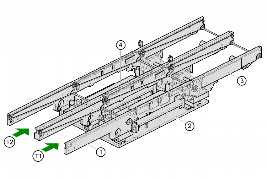
3.12.1 Structure
The conveyor belts are driven by DC motors. There is a lifting table for holding the PCBs in each
processing area. The width of the PCB conveyor can be adjusted either via the menu or using
the SIPLACE Pro computer.
Fig. 3.12 - 1 Structure of the dual conveyor
3.12.2 General
As the name suggests, the dual conveyor has two transport tracks, which are electrically and
mechanically independent of one another. In the Standard version, the right-hand side is the
fixed side. There is another version, however, in which the left-hand side is the fixed side.
(1) Input belt (2) Center belt
(3) Output belt (4) Lifting table
T1 Conveyor track 1 T2 Conveyor track 2

User Manual SIPLACE F5 HM 3 Technical data
Software Version SR.408.xx 03/2006 US Edition 3.12 PCB dual conveyor
99
There are two conveyor modes: Dual conveyor synchronous and "Dual conveyor asynchronous".
Enter the conveyor mode you wish to use in the machine data (konfig.ma).
3.12.3 Defining the conveyor tracks
The right transport track (viewed in the transport direction) is designated "Transport 1" and the
left as "Transport 2" (see Fig. 3.12 - 1
).
3.12.4 Changing transport mode
3
3
3.12.5 Asynchronous transport mode
3.12.6 Description
In asynchronous mode, only one PCB in a transport track is processed. At the same time,
another PCB in the second transport track is moved into the placement position. This saves the
full conveying time of one PCB, thus considerably increasing performance, particularly for PCBs
with a short cycle time.
3.12.7 Function
Once the machine has received the job data (panel, set-up), the PCBs on the feeding belts are
continuously transported to the available center conveyor (provided that the center belt is free)
throughout the placement operation. The placement sequence starts as soon as a PCB has
moved onto the center belt. The PCBs are processed one after another.
PLEASE NOTE 3
The components to be placed and the width of the PCBs must be identical on transport track 1
and 2. 3
If the placement sequence is interrupted, the conveyor interface will be disabled and the PCBs
currently on the center conveyor will be completed.
The conveyor interface is disabled or enabled simultaneously for both transport tracks.
Conveyor mode Entry in konfig.ma
Single conveyor 0
Dual conveyor, synchronous 1
Dual conveyor, asynchronous 2

3 Technical data User Manual SIPLACE F5 HM
3.12 PCB dual conveyor Software Version SR.408.xx 03/2006 US Edition
100
3.12.8 Synchronous transport mode
3.12.8.1 Description
In synchronous mode, two PCBs of the same size are simultaneously moved to the placement
position. They must be processed as a common panel.
In this way, the top and bottom of a PCB can be processed on a single line, and the time required
to transport the PCB is shorter since two PCBs are always transported at the same time.
3.12.8.2 Function
PCBs on conveyor tracks 1 and 2 are moved synchronously onto the conveyor sections (i.e. the
conveyors are controlled synchronously, but independently of one another). The components to
be placed on conveyor tracks 1 and 2 must be organized into a panel via two subpanels. (See
the SIPLACE Pro computer user manual).
If only one conveyor track (or center conveyor) is full when the placement sequence starts, the
subpanel on this section will be identified as “not for placement”.
3.12.9 Technical data for the dual conveyor
3
PCB format 50 x 50 mm² to 460 x 216.5 mm²
2" x 2" to 18" x 8.5"
Optional:
up to 508 x 216.5 mm²
up to 20" x 8.5"
PCB thickness 0.3 to 4.5 mm
Max. PCB warpage up: 4.5 mm - PCB thickness
down: 0.3 mm + PCB thickness
clearance on PCB underside 25 mm (standard), 40 mm (option)
PCB transport height 830 ± 15 mm (standard)
900 ± 15 mm (option)
930 ± 15 mm (option)
950 ± 15 mm (SMEMA option)
Type of interface Siemens (standard), SMEMA (option)
Component-free PCB handling edge 3 mm
PCB changeover time 2.5 s
Fixed conveyor side Right (standard), left (optional)
Components on each conveyor synchronous: same or different, asynchronous: same
PCB width on each conveyor synchronous: same or different, asynchronous: same