00191657-0102_UM_Luftkissentransportsystem_DE EN.pdf - 第50页
Operating Instruct ions Air cushion transporting system for SIPLACE 10/99 edition 8 Fig. 2 - 2 Diagram of the standard air cushion transporting s ystem 2 Compress ed air is supplie d to the air cus hion tra nsporting s y…
Air cushion transporting system for SIPLACE Operating Instructions
10/99 edition
7
2Overview
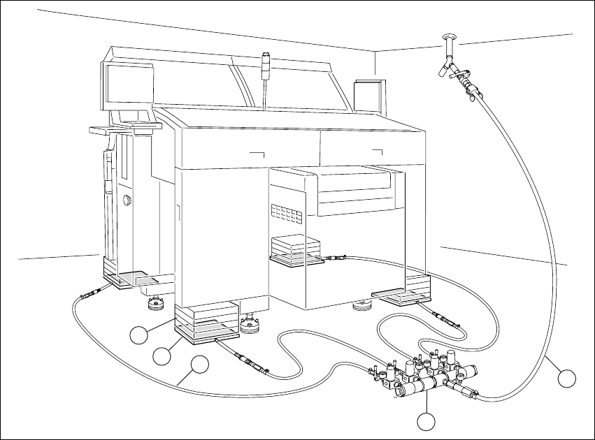
Fig. 2 - 1 Air cushion transporting system in position and ready for use.
2
The standard air cushion transporting system consists of:
(1) 4 air cushion modules
(2) Balancing boards
(3) 4 distributor hoses (2 x L = 4 m and 2 x L = 6 m)
(4) 1 control unit (with 4 pressure regulators, 5 manometers and 5 ball cocks)
(5) 10 m air hose with ball cock
(6) 1 Operating Instructions (English)
5
4
3
1
2
Operating Instructions Air cushion transporting system for SIPLACE
10/99 edition
8
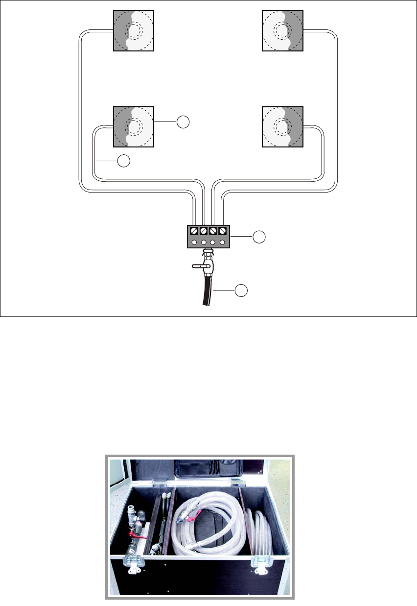
Fig. 2 - 2 Diagram of the standard air cushion transporting system
2
Compressed air is supplied to the air cushion transporting system from a central unit. The air
pressure is adjusted to suit the load on each air cushion by the associated pressure regulator (4). 2
The pressure regulator keeps the pressure at an almost constant level, while the air consumption
fluctuates slightly. 2
2
2
2
2
2
2
2
2
2
1
4
5
3
19
Air cushion transporting system for SIPLACE Operating Instructions
10/99 edition 3.1 Basic principles
9
3 Air cushion technology
3.1 Basic principles
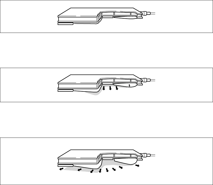
The effect of blowing in compressed air is as follows: 3
Fig. 3 - 1 The rubber bellows inflates
The ring-shaped rubber bellows inflates and fills the gap between the load to be transported and
the ground. 3
Fig. 3 - 2 The air cushion rises
Once the rubber bellows has created a seal with the floor, the air pressure in the space inside the
bellows increases, thus raising the air cushion and the load to be transported. 3
Fig. 3 - 3 The air cushion slides along
Air flows out between the rubber bellows and the floor, forming a thin film of air. The load slides
over this film with practically no friction. 3