00191657-0102_UM_Luftkissentransportsystem_DE EN.pdf - 第58页
Operating Instruct ions Air cushion transporting system for SIPLACE 4.4 Undulating and sloping surfaces 10/99 edition 16 4.4 Undul ating and sloping su rfaces Fig. 4.4 - 1 Undulating surface The air c ushion module s are…

Air cushion transporting system for SIPLACE Operating Instructions
10/99 edition 4.3 Surface index
15
4.3 Surface index
The following index system can be used to calculate the volume of air required to move a specific
load on different surfaces with the same friction. The theoretical initial value (index 1) relates to a
sheet of polished glass. An index of 3, for example, indicate that three times the volume of air is
required. 4
Tab. 4.3 - 1 Surface index
(The table also takes account of air losses due to porosity).
Surface Index
Clean sheet of glass (theoretical comparison value)1
Smooth, machine-polished floor, sealed 2
Smooth epoxy resin coating 1-2
Vinyl tiles (well laid and totally sealed joints) 1.5-2
Thin galvanized sheet 1.5-2
Hot-rolled sheet (with no rust or scale) 1-2
Pressboard, painted, smooth side 1-2
Painted chipboard 1-1.5
Manually smoothed concrete with visible grooves 3-5
Smooth concrete (unsealed) 2.5-4
"FAMA" bituminous concrete, smooth 2-3
Concrete, with wearing layer, smooth surface, not recommended
(possibility of cracking) 3- 4
Concrete with “broom finish” (unacceptable) 7-10
Asphalt road (unacceptable) 10-15
Operating Instructions Air cushion transporting system for SIPLACE
4.4 Undulating and sloping surfaces 10/99 edition
16
4.4 Undulating and sloping surfaces
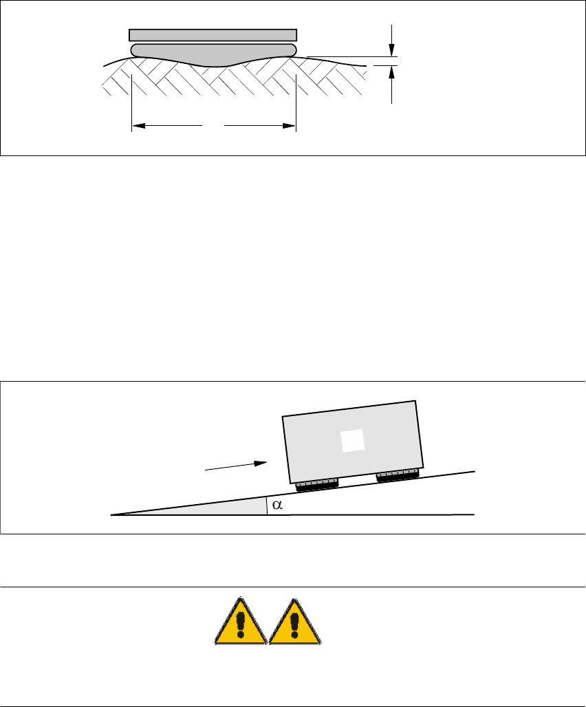
Fig. 4.4 - 1 Undulating surface
The air cushion modules are sufficiently flexible to be able to adapt to a gently undulating surface
to a limited extent. The difference in height must not exceed 2% of the diameter of the rubber
bellows, however. 4
Long undulations can be regarded as slopes. A load on the film of air will tend to slide to the lowest
point of its own accord on account of the low friction. The force required to hold the load in place
on a slope can be calculated as follows: 4
F = tg α · G (Dynamic forces must be added as well). 4
Fig. 4.4 - 2 Sloping surface
WARNING RISK OF CRUSHING 4
: In these situations, the load must be secured by means of drives, grippers, etc.
4
A ramp may be built in order to pass over door sills or steps, provided that the above values are
taken into account. 4
D
< 2% of D
F
G
Air cushion transporting system for SIPLACE Operating Instructions
10/99 edition 4.5 New floors
17
4.5 New floors
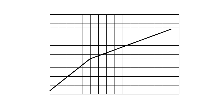
The flatness tolerances defined in DIN 18202 part 5, line 4 apply when building a floor suitable for
transporting loads with air cushions: 4
Fig. 4.5 - 1 Flatness tolerances for hall floors
The surface must be mechanically smoothed, sealed with varnish and given a plastic coating, if
necessary. 4
4.6 Old floors
The floor must conform to the flatness tolerances defined in DIN 18202. It is sometimes necessary
to add a screed layer in order to achieve this. It may also be necessary to burn off, grind or mill
the floor before laying the screed to ensure that the screed adheres well to the substrate. This also
applies if the floor is coated directly. 4
Good adhesion and an airtight surface coating is particularly important with screed floors and
other floor coverings such as plastic tiles, parquet, linoleum, vitrified tiles, etc. Even tiny cracks will
allow air to penetrate and then lift the coating away from the substrate. 4
1
5
1
0
5
0
123456789101112131415
Room length / width [m]
Unevenness [mm]