00191657-0102_UM_Luftkissentransportsystem_DE EN.pdf - 第52页
Operating Instruct ions Air cushion transporting system for SIPLACE 3.2 Structure of an air cushion module 10/99 edition 10 3.2 S tructure of an air cushion modul e An air c ushion m odule cons ists of a su pporti ng pla…
Air cushion transporting system for SIPLACE Operating Instructions
10/99 edition 3.1 Basic principles
9
3 Air cushion technology
3.1 Basic principles
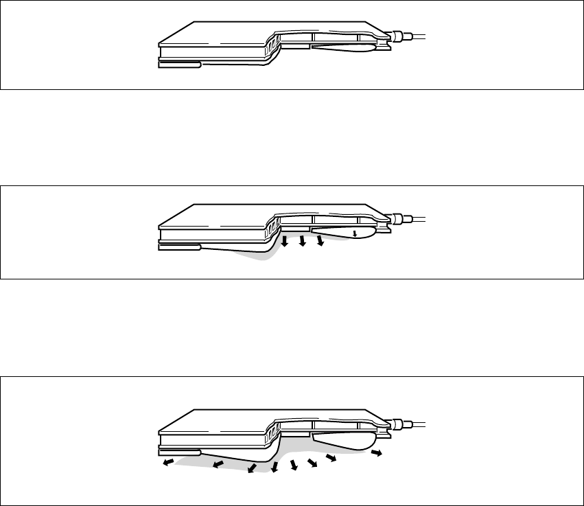
The effect of blowing in compressed air is as follows: 3
Fig. 3 - 1 The rubber bellows inflates
The ring-shaped rubber bellows inflates and fills the gap between the load to be transported and
the ground. 3
Fig. 3 - 2 The air cushion rises
Once the rubber bellows has created a seal with the floor, the air pressure in the space inside the
bellows increases, thus raising the air cushion and the load to be transported. 3
Fig. 3 - 3 The air cushion slides along
Air flows out between the rubber bellows and the floor, forming a thin film of air. The load slides
over this film with practically no friction. 3
Operating Instructions Air cushion transporting system for SIPLACE
3.2 Structure of an air cushion module 10/99 edition
10
3.2 Structure of an air cushion module
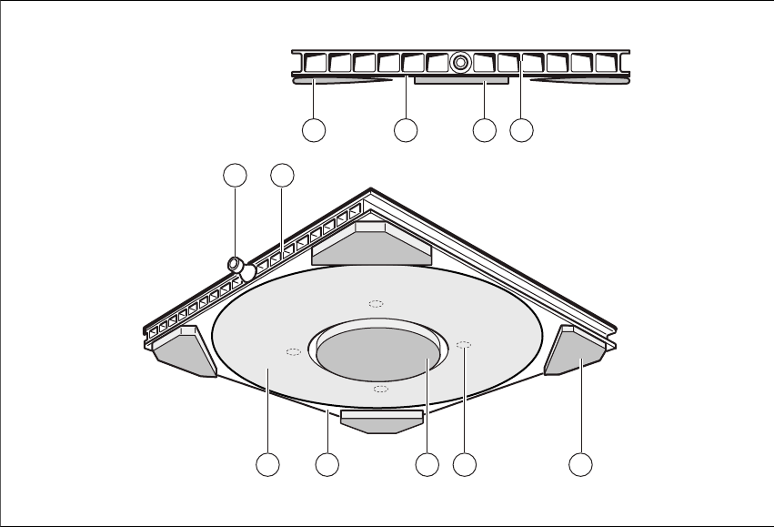
An air cushion module consists of a supporting plate (5) and an air cushion (1 – 4). 3
Fig. 3.2 - 1 Structure of the air cushion module
(1) Rubber bellows
(2) Aluminium plate
(3) Central support
(4) Corner support
(5) Load supporting plate
(6) Hose connecting nozzle
(7) Entry holes
The reinforced-fiber rubber bellows (1) is vulcanized onto the anodized aluminum plate (2). 3
When deflated, the air cushion rests on the central support (3). Larger air cushions are also
supplied with corner supports (4). 3
The air cushion is mounted in a rigid load supporting plate (5), again made from aluminum.
Together, the air cushion and load supporting plate form the air cushion module. 3
3421
56
1 2 3 5
7
Air cushion transporting system for SIPLACE Operating Instructions
10/99 edition 3.3 Connecting the module to the load
11
The unladen weight of the module is very small compared to its load-bearing capacity. 3
Air flows through the hose connecting nozzle (6) on the load supporting plate, via the entry holes
(7), and into the bellows and inner space of the air cushion. 3
3.3 Connecting the module to the load
The air cushion modules are generally inserted loosely beneath the load to be transported, e.g.
when moving machines (see figure 16 on page - 30), although they can also be used in holders
or fixed. 3