Micron Technical Reference V9 Volume 4.pdf - 第121页
TRANSPORTATION - MINOR RELOCATION INTRODUCTION Chapter Issue 2, Jul 16 Technical Reference Manual 42.1 CHAPTER 42 TRANSPORT A TION - MINOR RELOCA TION INTRODUCTION The following three chapters describe th e recommended p…
PREVENTIVE MAINTENANCE
CLEANING, LUBRICATION AND MAINTENANCE DIAGRAMS
41.14 Technical Reference Manual Chapter Issue 7, Jan 15
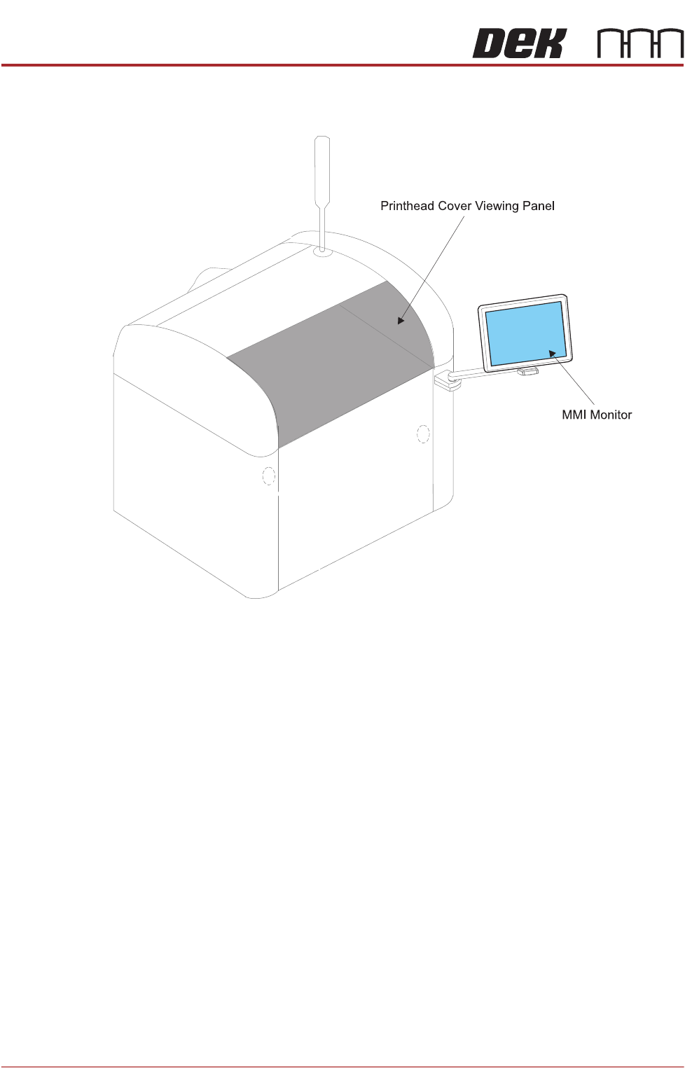
MMI and Printhead Cover

TRANSPORTATION - MINOR RELOCATION
INTRODUCTION
Chapter Issue 2, Jul 16 Technical Reference Manual 42.1
CHAPTER 42 TRANSPORTATION - MINOR RELOCATION
INTRODUCTION The following three chapters describe the recommended procedure for moving
or storing the machine:
• Minor Relocation - Moving the machine to another area within the factory
• Major Relocation - Moving the machine to another factory or storage
• Power Up - Must be performed after Minor or Major Relocation
The following procedure is utilized to minimize the risk of damage to the
machine when:
• The machine is brought out of line for servicing or fault rectification.
• The machine is being relocated a short distance from its original position,
ie within the confines of the factory on a pallet truck or similar manually
operated machine.
For major relocation, factory to factory moves, long term storage or where
excessive noise or vibration may affect the printer, refer to Transportation -
Major Relocation.
Machine
Preparation
1. With power applied to the machine, home the stencil actuators.
2. Switch OFF and disconnect the electrical power.
3. Disconnect the pneumatic supply.
4. Remove/open the rear printhead cover as detailed in the Covers chapter.
5. On Style 1 cover machines, remove the two upper side panels as detailed
in the Covers chapter.
TRANSPORTATION - MINOR RELOCATION
TRANSIT BRACKET INSTALLATION
42.2 Technical Reference Manual Chapter Issue 2, Jul 16
TRANSIT BRACKET INSTALLATION
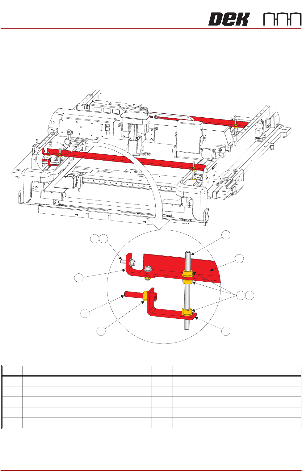
The figure below shows the transit brackets fully assembled for part identifica-
tion. Do not assemble off the machine, use the following procedure to assemble
the transit brackets on the machine.
Figure 42-1 Front and Rear Transit Brackets
NOTE
Item 5, the Left Chase Bracket is fitted upside down on dual lane machines.
Item Description Item Description
1 M8 Chase Stud 6 Transit Adjustment Screw Lock Nut
2 Front/Rear Transit Bracket 7 Transit Adjustment Screw
3 M8 Nut 8 Adaptor Bracket
4 M8 Washer 9 M5 Cap Head Screw
5 Left Chase Transit Bracket 10 M5 Washer
9
1
2
3
4
5
6
7
8
10