Micron Technical Reference V9 Volume 4.pdf - 第175页
TRANSPORTATION - MAJOR RELOCATION RELOCATION Chapter Issue 2, Jul 16 Technical Reference Manual 43.35 7. Adjust the height of each foot to approxima tely the same height, secure in place by tightening the nut s. NOTE Leg…
TRANSPORTATION - MAJOR RELOCATION
RELOCATION
43.34 Technical Reference Manual Chapter Issue 2, Jul 16
RELOCATION
Once the machine has been relocated, the machine can be unpacked and
reassembled using the following procedures.
Unpacking 1. Unscrew the transportation box securing screws and remove the lid and
sides.
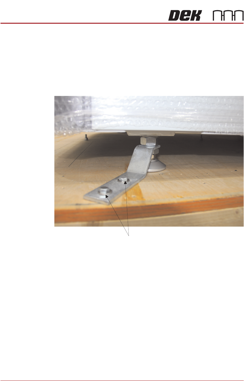
2. The printer is secured to the base of the transportation box with four brackets
each held in place using two M8 hex head woodscrews. Loosen the
machine leg M24 nuts and remove the M8 screws to remove the brackets.
3. Carefully insert the forklift forks to the rear of the machine. See the detail in
previous section, about the lifting capabilities of the machine used to perform
the lift and correct lift locations.
4. Raise the forks, separating the machine from the base of the transportation
box.
5. Between (and slightly forward of) the two rear mounting feet, locate the fifth
mounting foot.
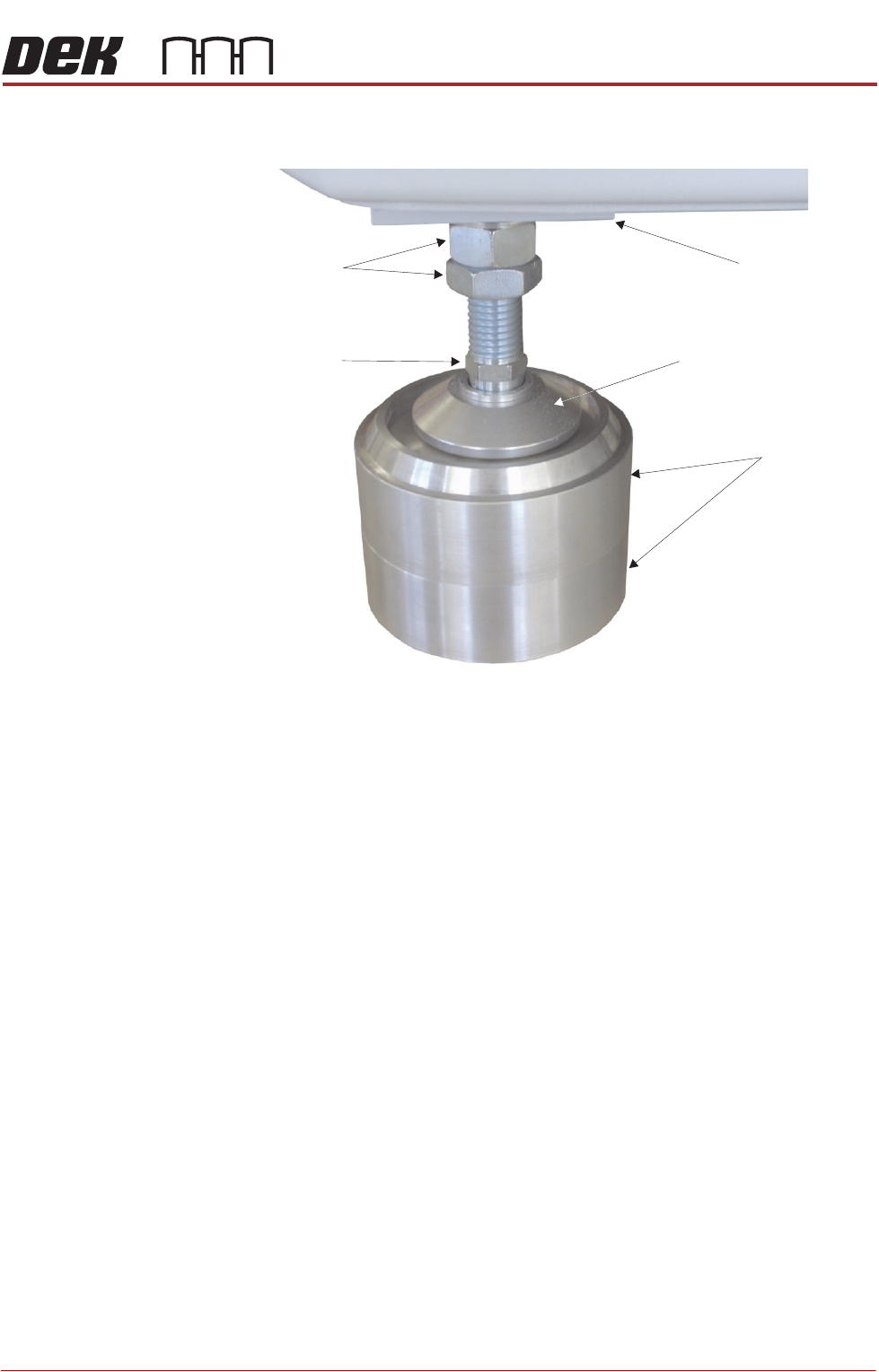
6. For machines with the anti-vibration mounting option, eight leg spacers and
one standard foot are supplied. Ensure the correct number of leg spacers
are fitted to the four corners of the machine when it is located into the
production line.
M 8 x 60 Woodscrews
TRANSPORTATION - MAJOR RELOCATION
RELOCATION
Chapter Issue 2, Jul 16 Technical Reference Manual 43.35
7. Adjust the height of each foot to approximately the same height, secure in
place by tightening the nuts.
NOTE
Leg spacers are shown here, but they are not used until the machine has
been moved to the designated position.
8. Move the machine to its designated position.
Leg Spacers
(2 shown)
Machine Mounting Foot
M24 Locking Nuts
Machine Frame
Leg Adjusting Nut
TRANSPORTATION - MAJOR RELOCATION
MACHINE SUPPLIES AND ENVIRONMENTAL CONDITIONS
43.36 Technical Reference Manual Chapter Issue 2, Jul 16
MACHINE SUPPLIES AND ENVIRONMENTAL CONDITIONS
Electrical
The machine operates on 100V to 240V ±10% 50/60Hz single phase ac mains.
ASM recommends a power supply capacity of 2.4KVA or greater.
ASM requires additional machine supply protection with the tment of an external double pole
circuit breaker conforming to national, federal or local legislation. ASM recommends that the
external circuit breaker is tted near the DEK printer and within easy reach of the operator. Use
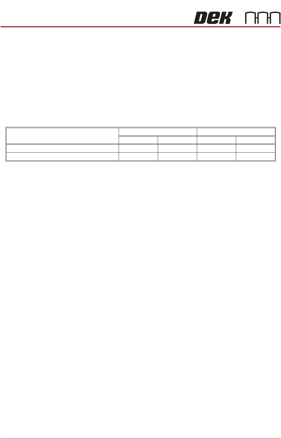
the following table to ensure the recommended circuit breaker is used:
Pneumatic Supply
The machine requires a pneumatic supply of clean, non lubricated air which should maintain a
minimum pressure of 5 Bar and a maximum of 8 Bar. The printer requires 5 litres/minute for
general use and a maximum of 226 litres/minute at 6 Bar.
The air should be to ISO 8573.1 standard, quality class 2.3.3.
Operating Conditions
The DEK printer must only be operated in the following operating envelope:
Indoors only
Unsuitable for use in wet locations
Temperature = 5 to 40°C (40 to 105°F)
Humidity = Maximum 80% Relative Humidity (non condensing)
Altitude = Maximum 2,000 metres (6,500 feet)
Pollution must comply to Degree 2
If the equipment is used in a manner not specied by the manufacturer, the protection provided
by the equipment may be impaired.
This equipment should be installed in accordance with the Installation Manual. ASM absolves
itself of all responsibility if the machine is not used within its operating envelope or for its
intended purpose.
NOTE
An over current circuit breaker protects the machine's internal wiring and components from
overheating or catching re during fault conditions. Under no circumstances must a circuit
breaker of value greater than 25 Amps be tted.
Transient overvoltages must not exceed those dened in Cat 2 of IEC 60364-4-443.
Voltage uctuations must not exceed 10% of nominal voltage.
115 Volts115 Volts 230 Volts
With Internal Vacuum UnitWithout Internal Vacuum Unit
230 Volts
Machine Current Consumption (approximately)
Value of Wall Mounted Circuit Breaker
20 Amps
25 Amps
6 Amps
10 Amps
10 Amps
13/16 Amps
3 Amps
4/6 Amps