Micron Technical Reference V9 Volume 4.pdf - 第27页
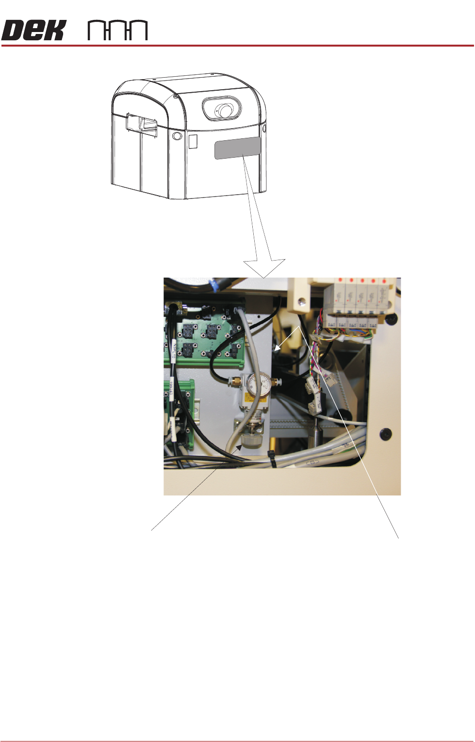
STINGER OVERVIEW Chapter Issue 2, Aug 14 Technical Reference Manual 38.3 Figure 38-1 Air Pressure Re gulator and Control Interface Location (Behind Rear Panel) Contro l I nterface (at rear of pane l ) Regu l ator
STINGER
OVERVIEW
38.2 Technical Reference Manual Chapter Issue 2, Aug 14
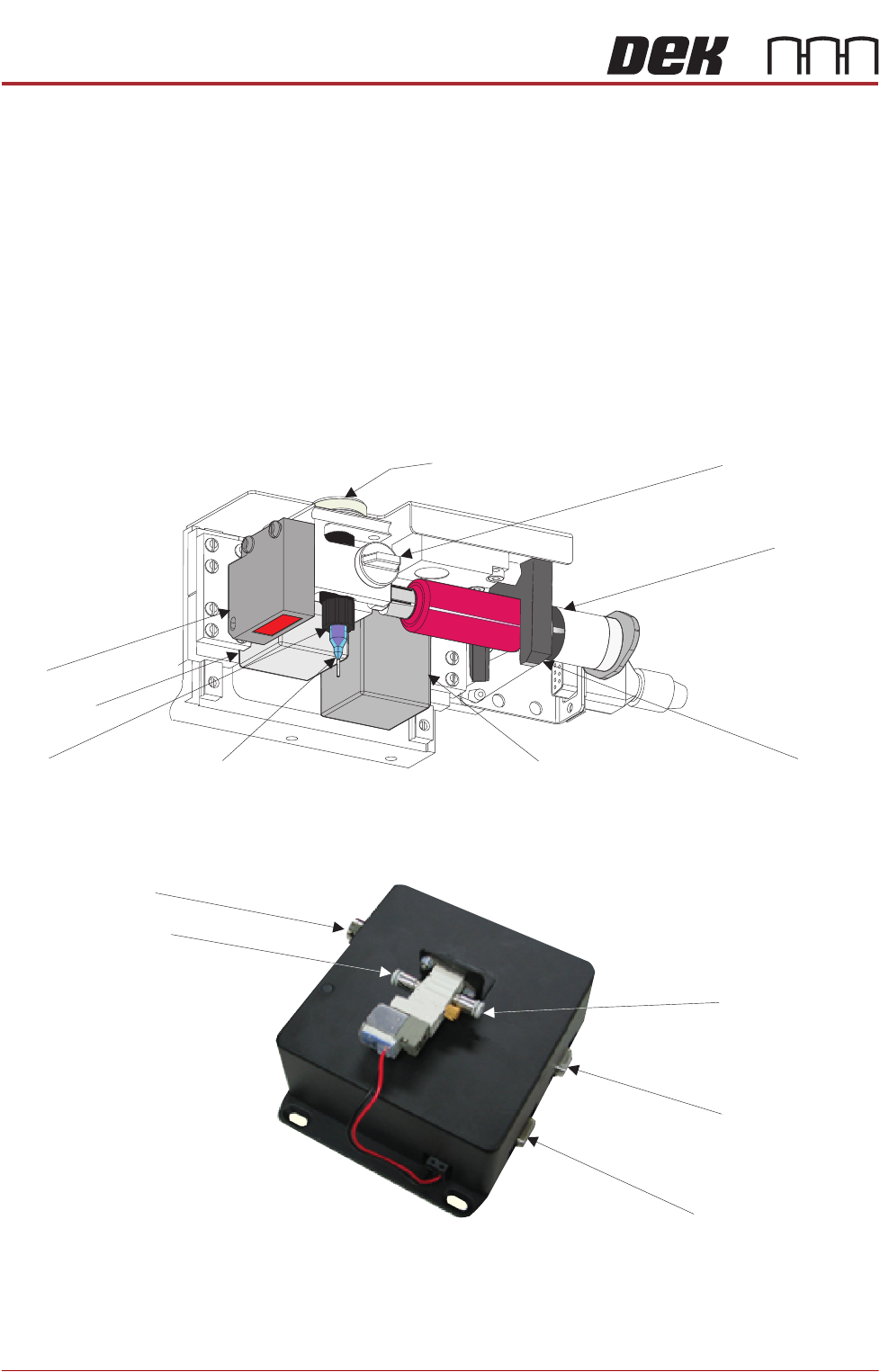
Elements The assembly comprises:
• Auger and auger drive motor
• 10cc Syringe and dispense nozzle
•Z-axis motor
• Laser light sensor
• Consumable low level sensor (not shown)
• Pneumatic regulator
• Electrical and pneumatic control interface
• Purge Station (optional) (not shown)
The syringe attaches to an auger valve at the outlet end and to a pneumatic
supply at its input. A ‘C’ shaped clamp holds the unit in position at the rear and
it is fixed at the front with a plastic clamp screw.
The control interface is mounted on the panel at the rear of the printer. It
provides all the electrical and the pneumatic control functionality. An air pres-
sure regulator sets pneumatic pressure.
Auger Clamp Screw
Auger Drive Gear
Z Axis Motor
‘C’ Clamp
10cc Syringe
Auger
Dispenser Nozzle
Auger Motor
Laser
Electrical Power In
Stinger Power & Signal
Serial RS232 to PC
Air Input Connector
Air Output Connector
Control Interface
STINGER
OVERVIEW
Chapter Issue 2, Aug 14 Technical Reference Manual 38.3
Figure 38-1 Air Pressure Regulator and Control Interface Location
(Behind Rear Panel)
Control Interface
(at rear of panel)
Regulator
STINGER
OVERVIEW
38.4 Technical Reference Manual Chapter Issue 2, Aug 14
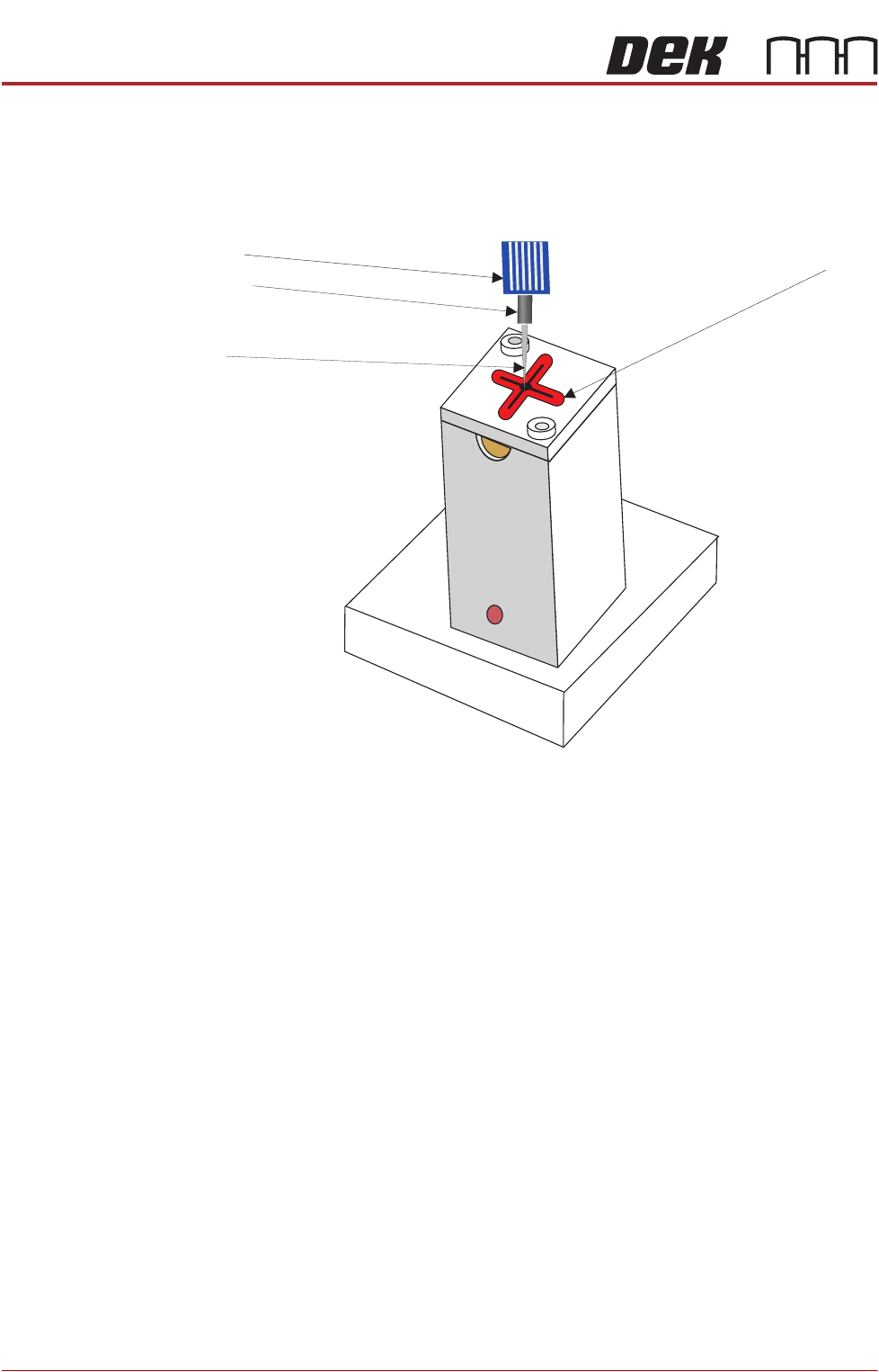
An optional purge station can be used to collect the purged adhesive. Parame-
ters are set up to centre the needle in the wiper target. The needle is fed into
the purge station and purging commences when the start purge button is
selected, and continues until the stop purge button is selected. If a purge station
isn’t used, purging takes place on a suitable area on the product.
Tip
Nozzle
Auger
Wiper
Target
Purge Station