Micron Technical Reference V9 Volume 4.pdf - 第87页
SENSORS INTRODUCTION Chapter Issue 5, Jan 16 Technical Reference Manual 40.1 CHAPTER 40 SENSORS INTRODUCTION This chapter gives details of the va rious sensors used in the machine. All sensors used on the machine fall wi…

DIAGNOSTICS
PASS THROUGH RAILS
39.36 Technical Reference Manual Chapter Issue 4, Aug 14
SENSORS
INTRODUCTION
Chapter Issue 5, Jan 16 Technical Reference Manual 40.1
CHAPTER 40 SENSORS
INTRODUCTION This chapter gives details of the various sensors used in the machine. All
sensors used on the machine fall within three categories, these are:
• Solid State Switch Sensors
• Conventional Switch Sensors
• Analogue Sensors
Solid State
Switches
The machine uses the following types of solid state sensor switches:
• Hall Effect Sensors
• Opto Sensors
• Ultrasonic Sensor
• Capacitive Proximity Sensor
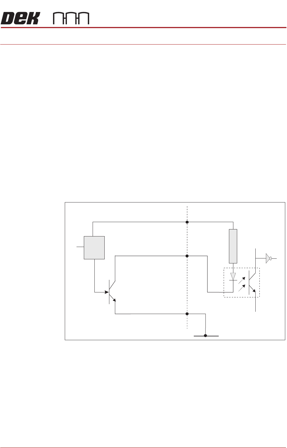
In all cases to initiate a logic 1 (on state) at the input, the sensor must connect
the signal input to 0V. This may not, however, translate to a positive condition
after software processing.
Figure 40-1 Typical Solid State Schematic
Testing Solid state sensors can only be tested in circuit as they require a logic supply
voltage and a pull up resistor on the sensor output.
1. Check for the 12V logic supply to the sensor.
2. Activate the sensor according to type and measure the voltage at the output
terminal with respect to 0V. The sensor output signal should change
between approximately 0V and 12V (see individual sensor descriptions for
more details).
Digital Input
+V
12V
Opto-isolator
1K8
0V
Signal I/P
Control
Circuit
Solid State
Sensor
SENSORS
INTRODUCTION
40.2 Technical Reference Manual Chapter Issue 5, Jan 16
Conventional
Switches
The machine uses the following types of conventional switch sensors:
• Reed Switch
• Safety Switch
• Microswitch
•Pressure Switch
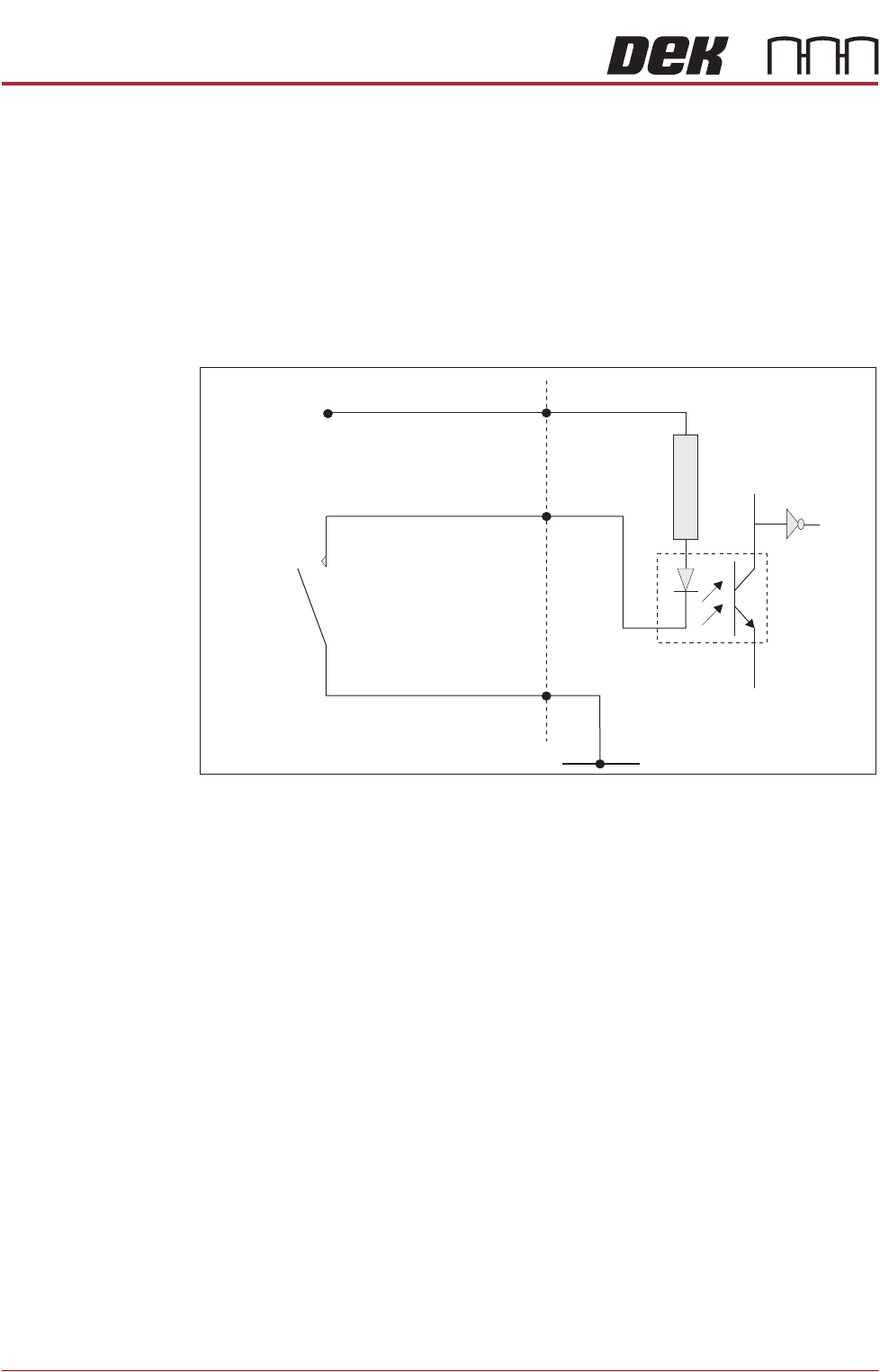
In all cases to initiate a logic 1 (on state) at the input, the sensor must connect
the signal input to 0V.
Figure 40-2 Typical Conventional Switch Schematic
Testing 1. Activate the sensor according to type and measure the voltage at the output
terminal with respect to 0V. The sensor signal output should change
between approximately 0V and 12V.
2. Remove switch from the circuit and measure continuity, when activated.
In all cases check digital inputs under diagnostics at the MMI.
Analogue Sensors The machine uses the following types of analogue sensor:
• Giant Magneto Resistive Sensor
• Strain Gauge Sensors
• Temperature and Humidity Sensor
Sensor Location Machine location for individual sensors are detailed in the respective module
chapter overview sections, ie Camera Y Home Sensor - can be found in the
Camera System Module chapter.
Digital Input
+V
12V
Opto-isolator
1K8
0V
Signal I/P
Conventional
Switch