Micron Technical Reference V9 Volume 4.pdf - 第244页
TRANSPORTATION - MAJOR RELOCATION MACHINE ASSEMBLY 43.104 Technical Re ference Manual Chapter Issue 2, Jul 16 13. Slide the angle brackets towards the machine cover , ensuring that either the vertical or sloping side as …
TRANSPORTATION - MAJOR RELOCATION
MACHINE ASSEMBLY
Chapter Issue 2, Jul 16 Technical Reference Manual 43.103
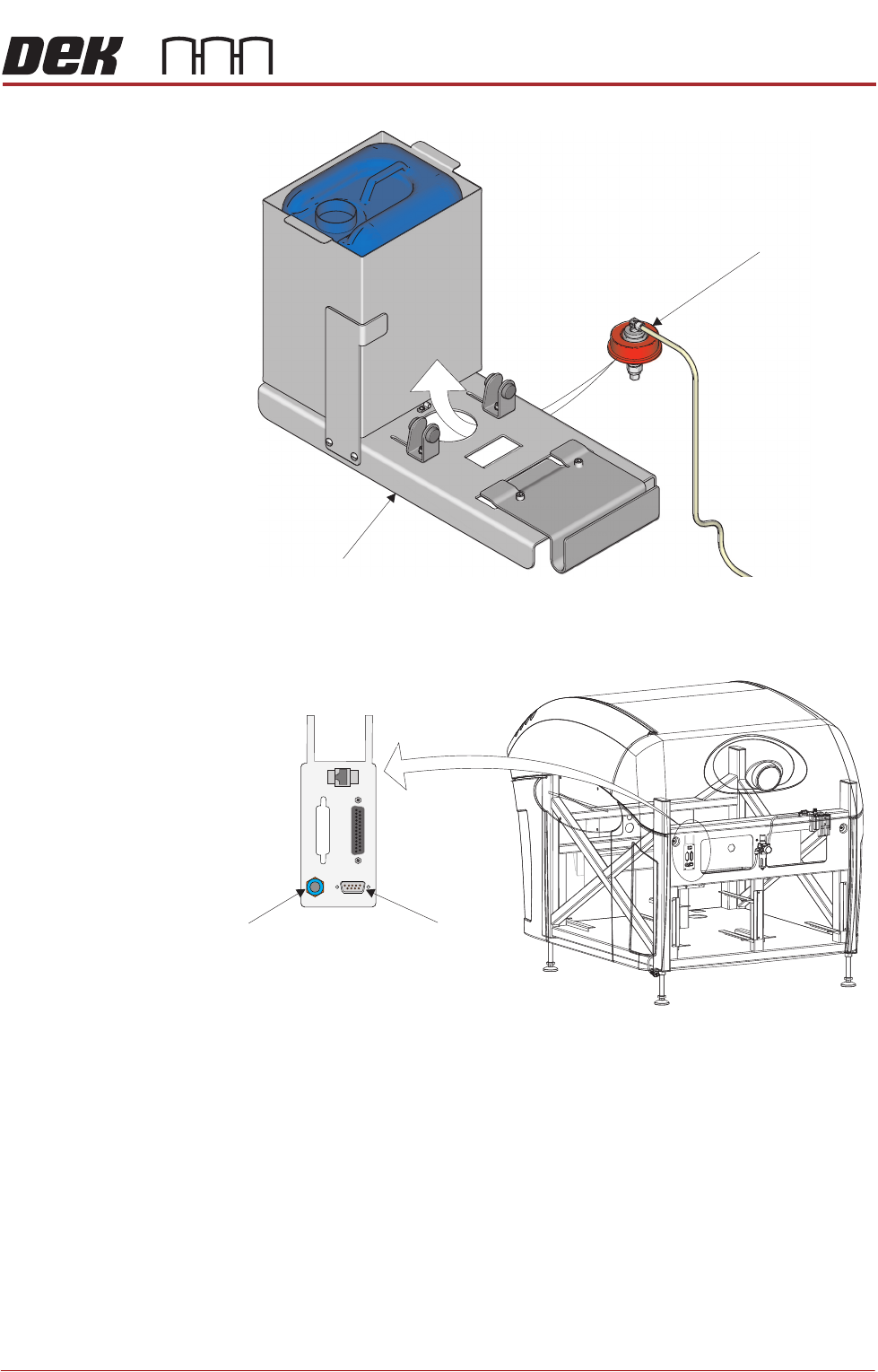
10. Fit the combined cap and 4mm tubing to the solvent container.
11. Connect the cable from the external solvent tank to 9SK69 on the external
services panel.
12. Fit the rear cover (front cover on style 4 machines).
Solvent Container Cap
Base Plate
View on Rear of Machine
POWER ON
PART No. 160740
M/C AVAILABLE
BOARD AVAILABLE
BOARD PASS
D
O
W
N
L
IN
E
BOARD AVAILABLE
BOARD PASS
M/C AVAILABLE
U
P
L
IN
E
FMI POD
Solvent Fluid
Connector
Solvent Sensor
9SK69
TRANSPORTATION - MAJOR RELOCATION
MACHINE ASSEMBLY
43.104 Technical Reference Manual Chapter Issue 2, Jul 16
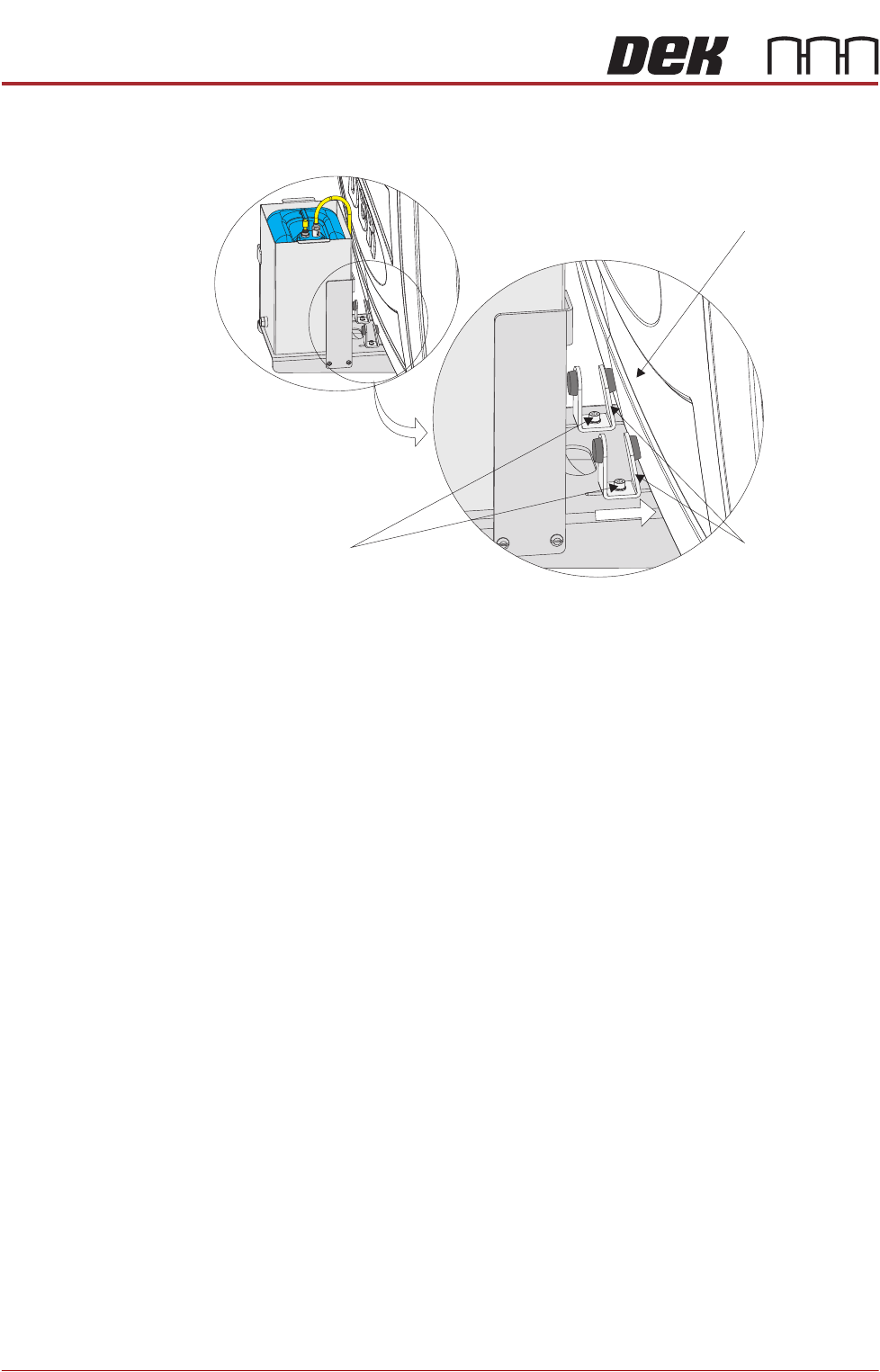
13. Slide the angle brackets towards the machine cover, ensuring that either the
vertical or sloping side as appropriate, abuts the machine cover.
14. Tighten the two M5 cap head securing screws.
Tooling and Print
Medium
Applicators
Any material applicator or tooling removed from the machine prior to it’s move
should be refitted. Refer to the individual item chapter or the tutorial set supplied
with the machine.
Power Up On completion of relocation, carry out the procedure in the Transportation -
Power Up chapter.
Machine Cover
Securing Screws
Angle Brackets
TRANSPORTATION - POWER UP
PRE POWER UP CHECKS
Chapter Issue 1, Jan 16 Technical Reference Manual 44.1
CHAPTER 44 TRANSPORTATION - POWER UP
PRE POWER UP CHECKS
Electrical Test Before the machine is connected to the factory electrical supply, the following
electrical tests must be performed:
1. Ensure the mains isolator switch is in the OFF position.
2. Remove the front cover of the machine to gain access to the mains isolator
switch.
3. Remove the front cover of the mains isolator switch.
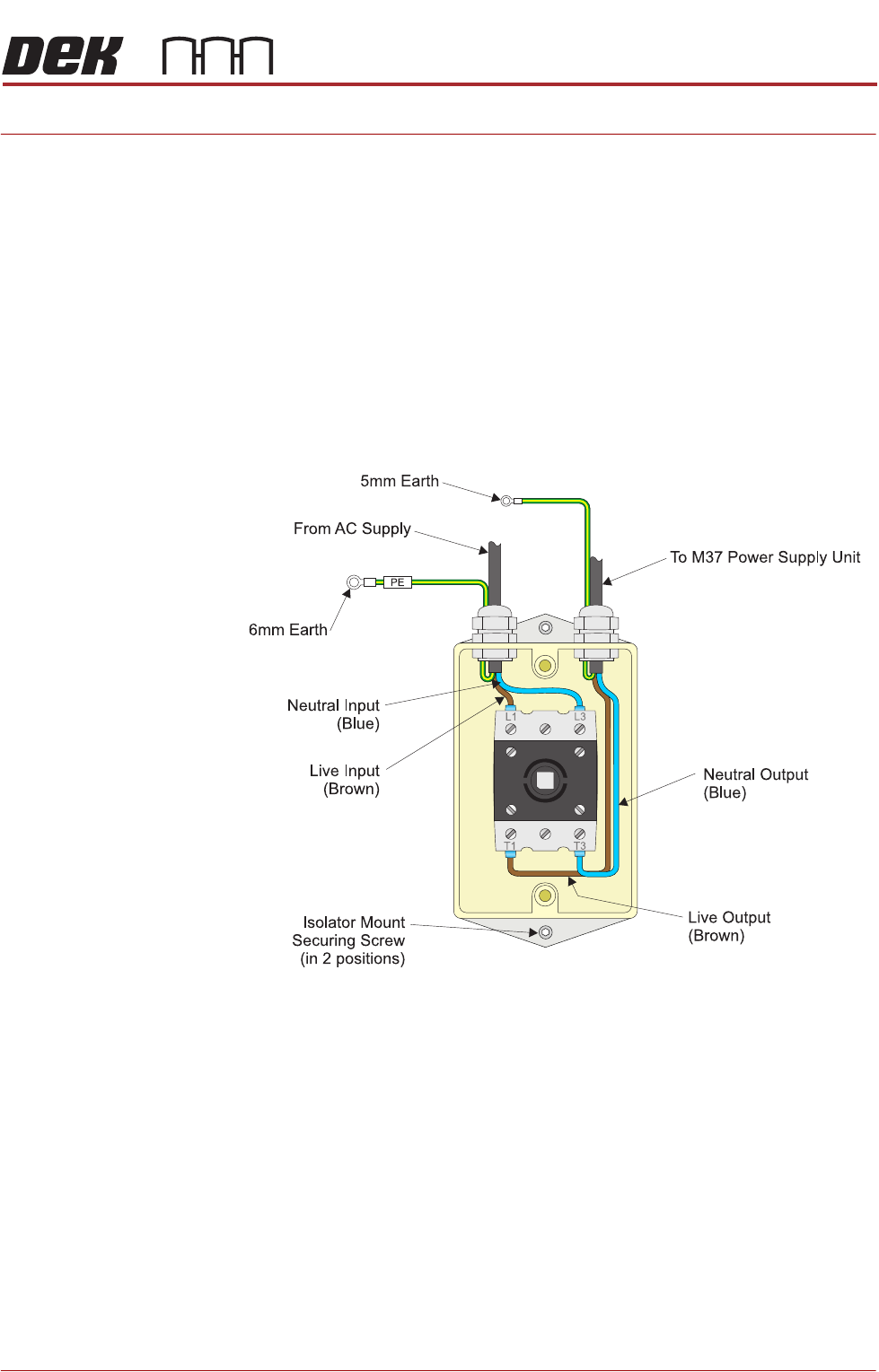
4. Perform a visual inspection of the mains isolator switch ensuring the follow-
ing:
a. The earth input and earth output cables are connected to the earth tag.
b. The live input is connected to the top of the isolator switch on the left hand
side.
c. The live output is connected to the bottom of the isolator switch on the left
hand side.
d. The neutral input is connected to the top of the isolator switch on the right
hand side.
e. The neutral output is connected to the bottom of the isolator switch on the
right hand side.
5. Ensure that all six cables are secure and no bare wires are showing.
6. Connect the two probes of a digital volt meter (DVM) together and ensure
that the DVM is reading 0Ω.