Micron Technical Reference V9 Volume 4.pdf - 第250页
TRANSPORTATION - POWER UP PRE POWER UP CHE CKS 44.6 Technical Reference Manual Chapter Issue 1, Jan 16 Pneumatic Supply The machine requires a pneumat ic supply o f clean, non lubricated air which should maintain a minim…
TRANSPORTATION - POWER UP
PRE POWER UP CHECKS
Chapter Issue 1, Jan 16 Technical Reference Manual 44.5
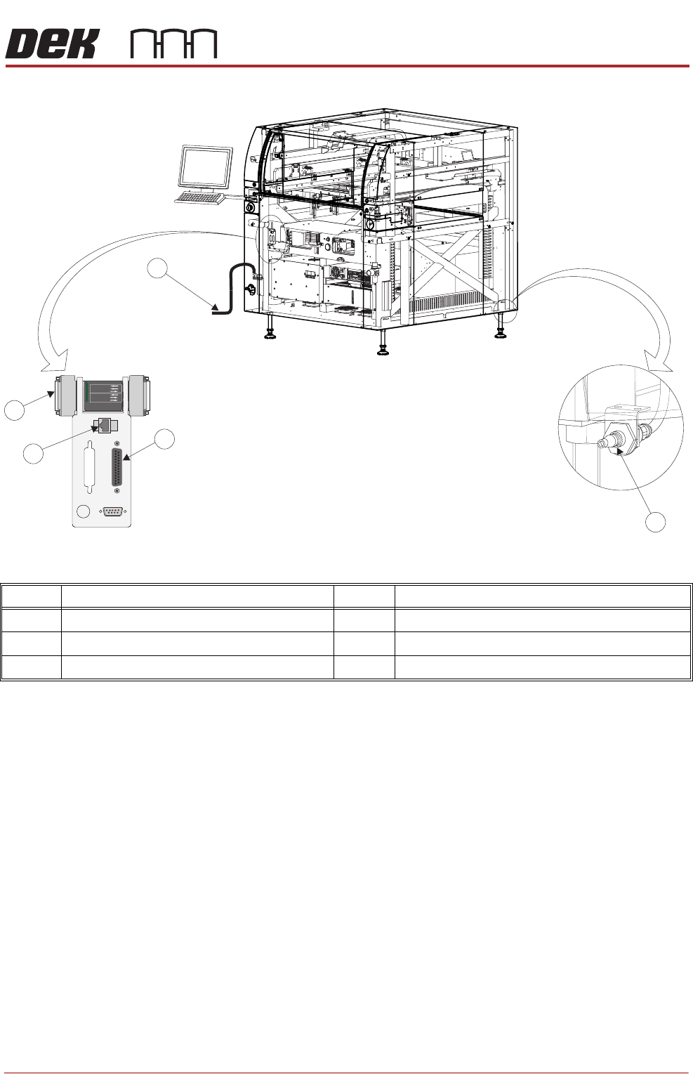
Figure 44-2 Style 4 Machine
In order for the machine to function correctly the following services must be
available:
• Pneumatic Supply
• Electrical Supply
Other services that may be required are:
• Host Communications
• Upline/Downline Machine Interface (FMI)
Item Description Item Description
1 Printer Mains Supply Cable 4 Host Comms Lan RJ45
2 Air Connection 5 Foreign Machine Interface (FMI) Pod
3 Temperature Control Module (TCM)
POWER ON
PART No. 160740
M/C AVAILABLE
BOARD AVAILABLE
BOARD PASS
D
O
W
N
L
IN
E
BOARD AVAILABLE
BOARD PASS
M/C AVAILABLE
U
P
L
IN
E
FMI POD
Front Right Quarter View
1
3
4
5
2
TRANSPORTATION - POWER UP
PRE POWER UP CHECKS
44.6 Technical Reference Manual Chapter Issue 1, Jan 16
Pneumatic Supply The machine requires a pneumatic supply of clean, non lubricated air which
should maintain a minimum pressure 5 Bar and a maximum of 8 Bar.
The air should be to ISO 8573.1 standard, quality class 2.3.3, where:
• 2 dirt = 1 micron
• 3 water = -20°C pressure dewpoint
• 3 oil = 1mg/m3
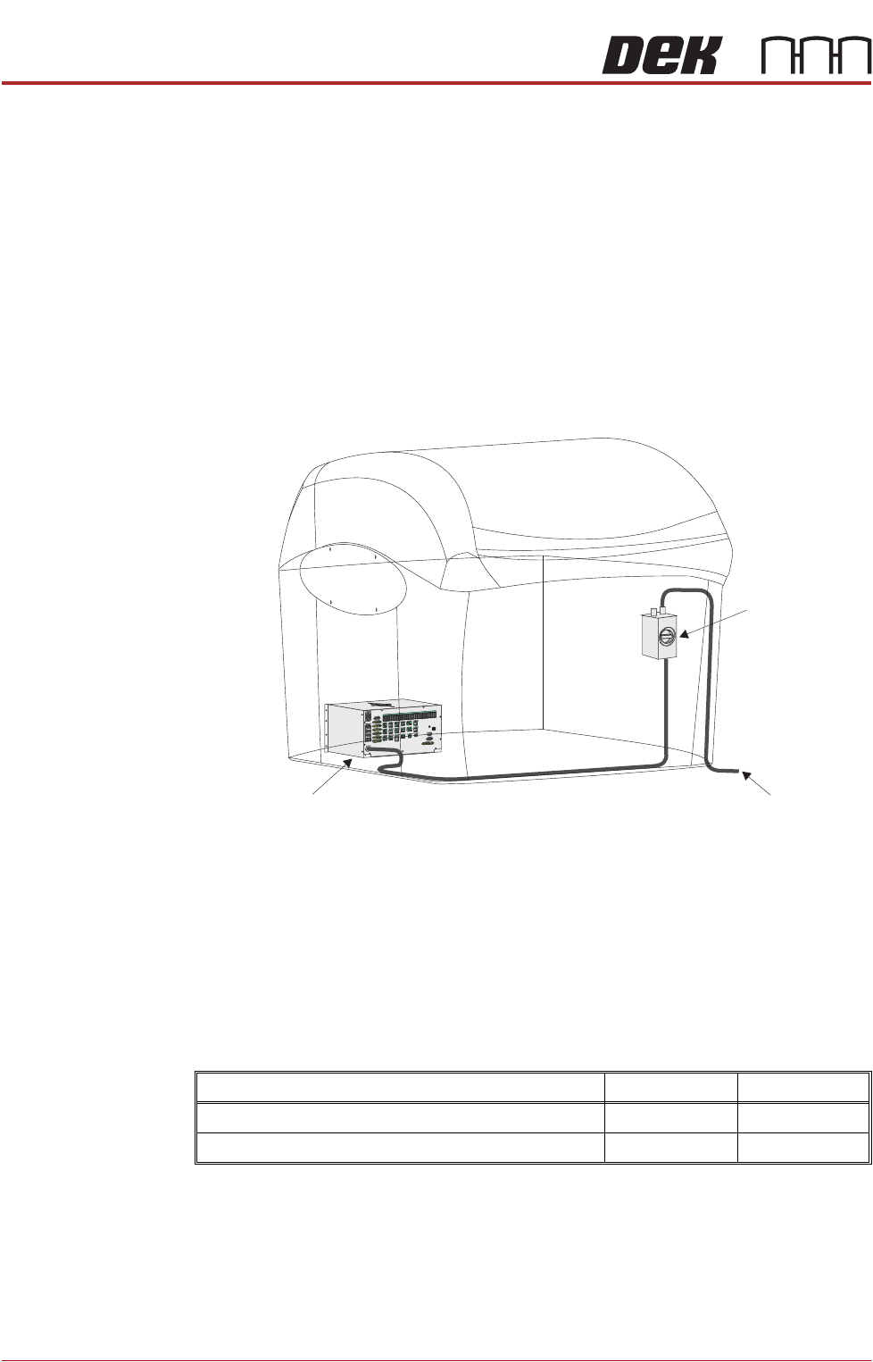
Electrical Supply The factory mains supply for the machine is routed through the front panel
mounted mains isolator switch and on to the M37 power supply enclosure where
various low voltages are distributed throughout the machine.
Figure 44-3 Mains Electrical Supply
The machine operates on 100V to 240V ± 50/60Hz single phase ac mains.
ASM recommends a power supply capacity of 2.4KVA or greater.
ASM requires additional machine supply protection with the fitment of an
external double pole circuit breaker conforming to national, federal or local
legislation. Use the following table to ensure the recommended circuit breaker
is used:
NOTE
An over current circuit breaker protects the machines internal wiring and
components from overheating or catching fire during fault conditions. Under no
circumstances must a circuit breaker of value greater than 25 Amps be fitted.
110 to 130 Volts 210 to 240 Volts
Wall Mounted Circuit Breaker (with Vacuum Unit) 25 Amp 13/16 Amp
Wall Mounted Circuit Breaker (without Vacuum Unit) 10 Amp 4/6 Amp
To Factory Mains Supply
Mains Isolator
Switch
M37 Power Supply Enclosure

TRANSPORTATION - POWER UP
PRE POWER UP CHECKS
Chapter Issue 1, Jan 16 Technical Reference Manual 44.7
Preparations 1. Ensure machine mains isolator is OFF.
2. Check and verify that the mains electrical supply is single phase 100V to
240V ±10% at 50/60Hz ac.
3. Check that all circuit breakers are in the ON position.
4. Ensure that all access covers and removable panels are closed and are in
place.
5. Ensure that the E Stop button is in the fully out position. To check this, push
the E Stop button until it latches. Turn the button clockwise to release it.