Micron Technical Reference V9 Volume 4.pdf - 第26页
STINGER OVERVIEW 38.2 Technical Reference Manual Chapter Issue 2, Aug 14 Element s The assembly comprises: • Auger and auger drive motor • 10cc Syringe and dispense nozzle •Z - a x i s m o t o r • Laser light sensor • Co…
STINGER
OVERVIEW
Chapter Issue 2, Aug 14 Technical Reference Manual 38.1
CHAPTER 38 STINGER
OVERVIEW
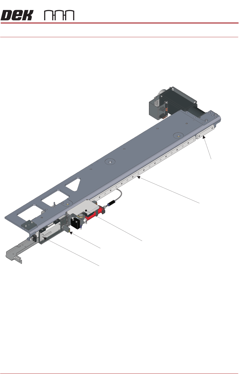
Stinger is a glue dot dispenser module attached to the camera carriage. The
dispensed adhesive is used to hold larger mass components, which may as a
result of transportation, or where under components are used, move after
placement.
After product has been printed, stinger dispenses adhesive in a pre-pro-
grammed pattern onto the product’s surface. A laser can be programmed to
take a measurement at various locations on the product; these measurements
are used to check that the dispense gap is maintained, even where product
warpage exists.
Camera Carriage
USC Bracket Location
(bracket not shown)
Stinger Assembly
Camera Mount
(camera not shown)
Board Stop Sensor
STINGER
OVERVIEW
38.2 Technical Reference Manual Chapter Issue 2, Aug 14
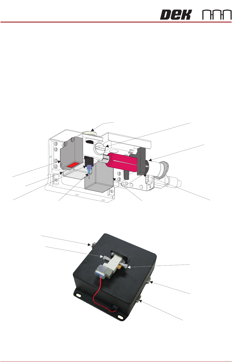
Elements The assembly comprises:
• Auger and auger drive motor
• 10cc Syringe and dispense nozzle
•Z-axis motor
• Laser light sensor
• Consumable low level sensor (not shown)
• Pneumatic regulator
• Electrical and pneumatic control interface
• Purge Station (optional) (not shown)
The syringe attaches to an auger valve at the outlet end and to a pneumatic
supply at its input. A ‘C’ shaped clamp holds the unit in position at the rear and
it is fixed at the front with a plastic clamp screw.
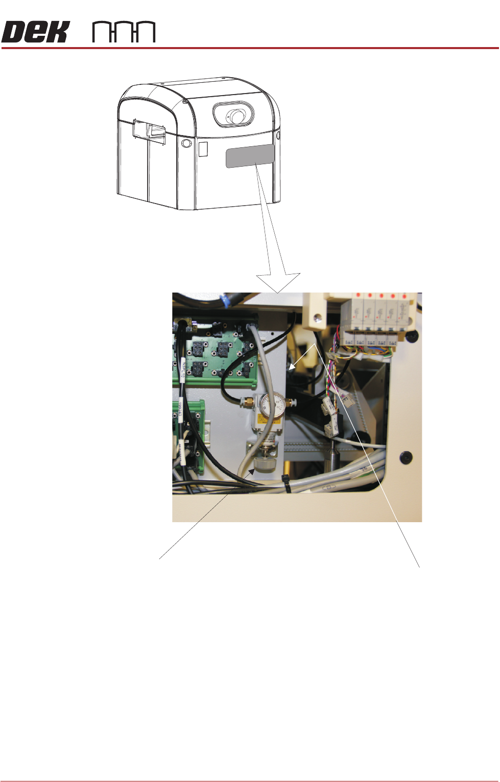
The control interface is mounted on the panel at the rear of the printer. It
provides all the electrical and the pneumatic control functionality. An air pres-
sure regulator sets pneumatic pressure.
Auger Clamp Screw
Auger Drive Gear
Z Axis Motor
‘C’ Clamp
10cc Syringe
Auger
Dispenser Nozzle
Auger Motor
Laser
Electrical Power In
Stinger Power & Signal
Serial RS232 to PC
Air Input Connector
Air Output Connector
Control Interface
STINGER
OVERVIEW
Chapter Issue 2, Aug 14 Technical Reference Manual 38.3
Figure 38-1 Air Pressure Regulator and Control Interface Location
(Behind Rear Panel)
Control Interface
(at rear of panel)
Regulator