Micron Technical Reference V9 Volume 4.pdf - 第141页
TRANSPORTATION - MAJOR RELOCATION PREPARATION Chapter Issue 2, Jul 16 Technical Reference Manual 43.1 CHAPTER 43 TRANSPORT A TION - MAJOR RELOCA TION PREP ARA TION The following chapter describes the recommende d procedu…
TRANSPORTATION - MINOR RELOCATION
MACHINE HEIGHT AND LEVELLING
42.20 Technical Reference Manual Chapter Issue 2, Jul 16
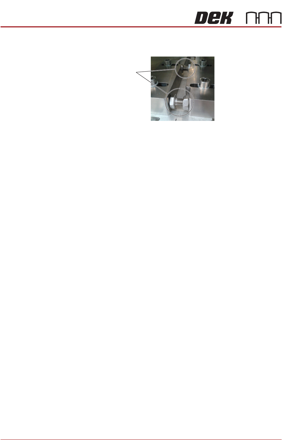
30. Rotate the stopper bolts by hand until they make contact with the opposing
block, and then secure them using the locknuts.
31. Move Machine A back into position locating foot (3) into V-Block.
32. Position locating foot (4) against Locating Block.
33. Recheck the machine is level.
34. Recheck the machine height has not been disturbed.
Power Up On completion of relocation, carry out the procedure in the Transportation -
Power Up chapter.
Stopper Bolts

TRANSPORTATION - MAJOR RELOCATION
PREPARATION
Chapter Issue 2, Jul 16 Technical Reference Manual 43.1
CHAPTER 43 TRANSPORTATION - MAJOR RELOCATION
PREPARATION
The following chapter describes the recommended procedure to prepare the
machine for transportation from its originally installed position to minimize the
risk of damage to the machine during transportation.
This procedure is fully detailed, illustrating every aspect of transporting a
machine safely when:
• Machine relocation is to another site outside the original factory
• The machine is being stored
• If the machine has to experience any substantive shocks or vibration
NOTE
If the machine is being stored or moved to another location, it is recommended
that the machine is packaged in its original packing crate.
Machine Prior to installing transit brackets to the machine ensure the following:
1. With power applied to the machine:
a. Drive the rails to 40mm board width.
b. Home the stencil actuators.
2. Shut down the printer software.
3. Switch off and disconnect the electrical power.
4. Disconnect the air supply.
5. Remove/open the rear printhead cover.
6. On Style 1 or 2 cover machine, remove the two upper side panels as detailed
in the Covers chapter.
TRANSPORTATION - MAJOR RELOCATION
PREPARATION
43.2 Technical Reference Manual Chapter Issue 2, Jul 16
Grease Protection
WARNING
BOARD CLAMPS. EXTREME CARE MUST BE EXERCISED WHEN WORKING IN
THE TOOLING AREA OF THE MACHINE TO AVOID INJURY. THE FOILS ON THE
FRONT AND REAR BOARD CLAMPS ARE VERY SHARP.
If the machine is being relocated to another site or placed into storage, bare
metal surfaces must be greased to protect against corrosion. Using a small
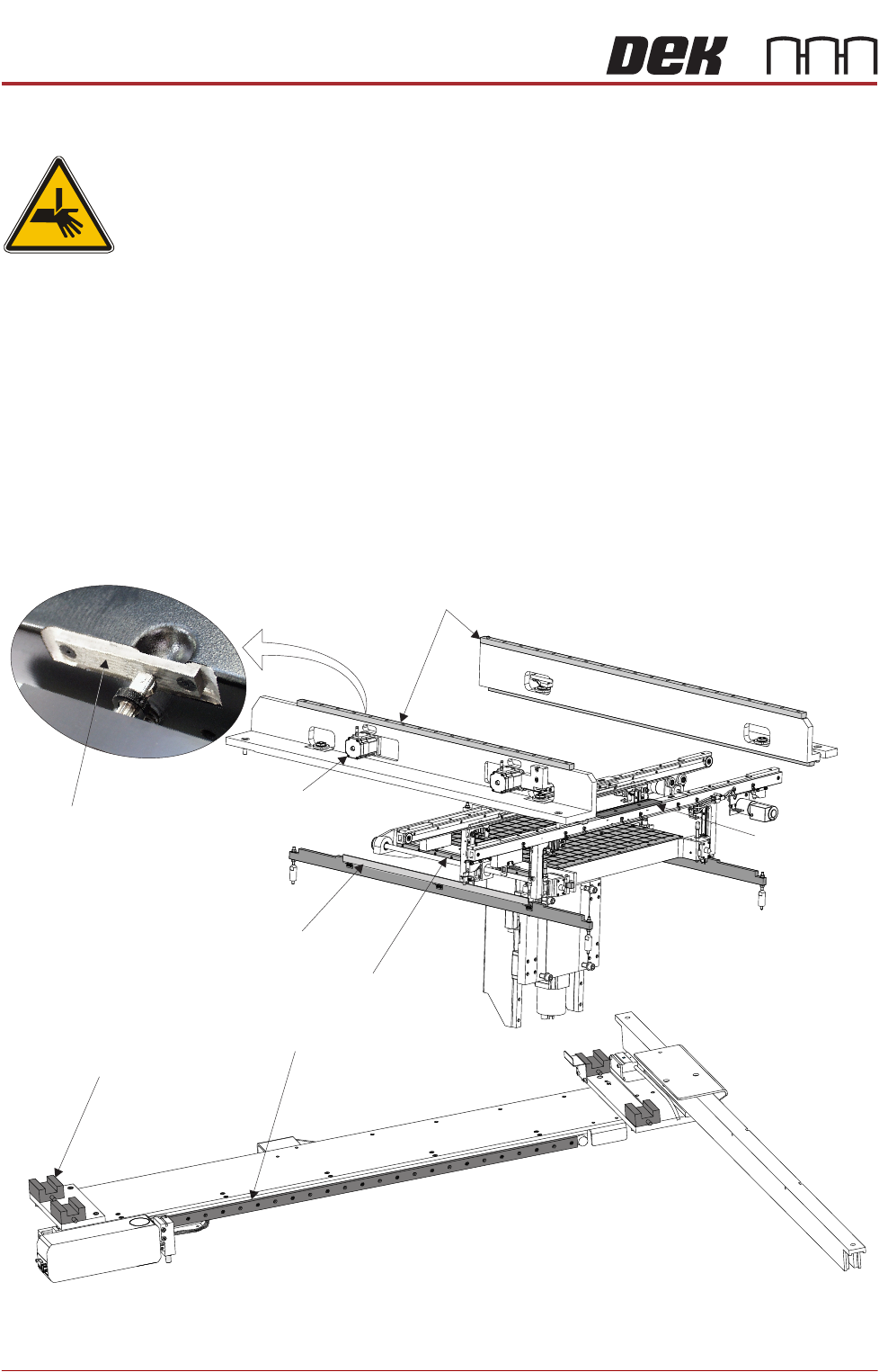
brush or cloth, apply LM grease to the following areas:
• Print carriage linear bearing guides (above the printheads)
• Camera linear bearing guides (below the printheads)
• Rear moving rail linear bearing guides (either side of the rising table)
• Top face of both clatter bars (either side of the rising table)
• Actuator striker plates (in 3 positions)
• Front and rear board clamps
Figure 43-1 Grease Protection
Print Carriage Linear Bearing Guides
Moving Rail Linear Bearing Guide (in 2 positions)
Clatter Bar (in 2 positions)
Board Clamp
(in 2 positions)
Camera Linear Bearing GuideX
Camera Linear Bearing GuideY
(4 Positions)
Actuator (in 3 positions)
Actuator Striker Plate
(in 3 positions)