00196062-03_SM_LDU-X_EN.pdf - 第33页
4 Service Work 4.2 Replacing Spare Parts Service Manual SIPLACE LDU-X Linear Dipping Unit 11/2017 33 Installation 1. Display board 2. Display housing 3. Switch on the display board 4. Studs (bumps) on the buttons CAUTI…
4 Service Work
4.2 Replacing Spare Parts
32 Service Manual SIPLACE LDU-X Linear Dipping Unit 11/2017
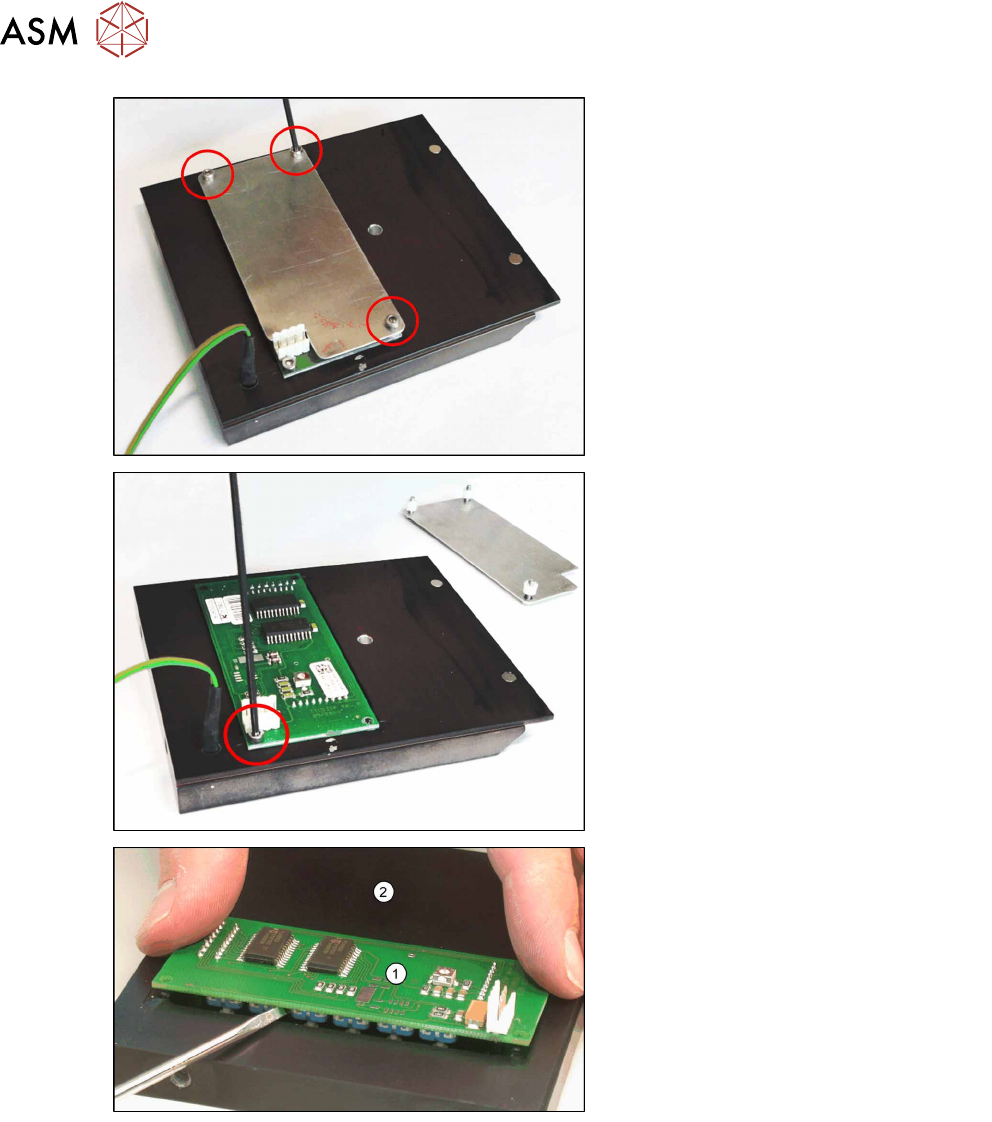
► Loosen the 3 screws fastening the
cover plate.
► Loosen the screws fastening the dis-
play board.
► Gently lever the board (1) out of the
display housing (2) e.g. with a flat
screwdriver.
4 Service Work
4.2 Replacing Spare Parts
Service Manual SIPLACE LDU-X Linear Dipping Unit 11/2017 33
Installation
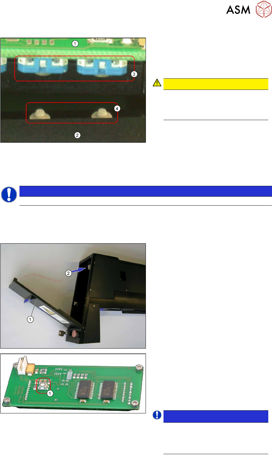
1. Display board
2. Display housing
3. Switch on the display board
4. Studs (bumps) on the buttons
CAUTION!
During the installation make sure that
the studs (bumps) (4) on the buttons
properly clip into the switch cavities
(3) on the display board.
.
► Further installation is performed by following the above instructions in the reverse order.
► Check the contrast of the display after the replacement and adjust it correctly if required.
4.2.12 Setting the Display Contrast
NOTICE
The display contrast cannot be set for an LDU-X with re-fill unit.
Equipment required
●
Small screwdriver
Setting the contrast
► Place the LDU-X onto the machine.
► Switch the LDU-X on.
► Open the front flap (1) of the LDU-X,
so that the underside of the display
unit(2) is accessible.
Display board
The display board is located on the under-
side of the display. This has a rotary en-
coder (1) (potentiometer) for the display
contrast.
► Use the small screwdriver to set the
rotary encoder so that the display can
be read easily.
NOTICE!
Optimum setting
The setting is correct when you can
no longer see the gray segments be-
hind the numbers.
.
4 Service Work
4.2 Replacing Spare Parts
34 Service Manual SIPLACE LDU-X Linear Dipping Unit 11/2017
4.2.13 Replacing the Display Foil
Overview
Equipment required
●
Standard tools
●
Allen key size 2 and 5
●
Lint-free cleansing tissues
●
Ethanol
●
Spare part: Display foil [03063561-xx] (self-adhesive, on paper)
Removal
► Dismantle the display unit and remove the display board. (See 4.2.11 "Replacing the Display
Board" [}31])
► The display foil is attached to the housing. Carefully remove the foil from the housing with a
sharp object (knife, chisel).
► Remove all residual adhesive from the housing. Use a knife and a cloth moistened with eth-
anol.
Installation
► Take the new display foil and remove the protective sheet on the underside of the foil. The ad-
hesive surface is now uncovered.
► Position the new display foil correctly on the housing and press firmly into place.
► Further installation is performed by following the above instructions in the reverse order.
4.2.14 Replacing the Service Switch
Overview
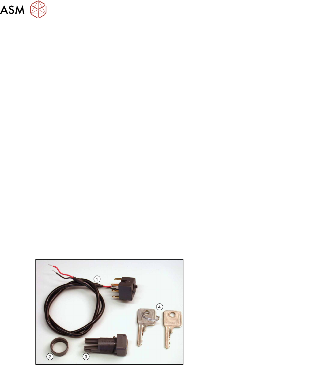
Service switch [03062342-xx]
1. Cable to LDU-X controller
2. Plastic nut
3. Service switch
4. Key
Equipment required
●
Standard tools
●
Allen key size 6
●
Cable tie
●
Spare part: Service switch [03062342-xx] (incl. switch unit with cable, plastic nut and 2 keys)