00196062-03_SM_LDU-X_EN.pdf - 第56页
4 Service Work 4.2 Replacing Spare Parts 56 Service Manual SIPLACE LDU-X Linear Dipping Unit 11/2017 4.2.28 Replacing the cable for the display board - control board Overview Cable display board - control board [03066594…
4 Service Work
4.2 Replacing Spare Parts
Service Manual SIPLACE LDU-X Linear Dipping Unit 11/2017 55
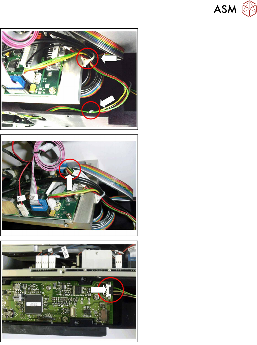
► Open the two cable ties marked in the
diagram.
► Pull the connector for the "cable X ad-
apter - control board" vertically up and
out of the connection for the LDU-X
control board.
► Pull the connector for the "cable X ad-
apter - control board" sideways and
out of the connection for the X ad-
apter - control board.
Installation
Installation is performed by following the same instructions in the reverse order.
► Plug the black connector for the "cable X adapter - control board" sideways into the connec-
tion for the X adapter - control board.
► Plug the white connector for the "cable X adapter - control board" vertically into the connection
for the LDU-X - control board.
► Replace the two cable ties which you removed earlier on.
► Fit the left side cover into place (see section 4.2.29.10 "Fitting the Side Covers" [}65]).

4 Service Work
4.2 Replacing Spare Parts
56 Service Manual SIPLACE LDU-X Linear Dipping Unit 11/2017
4.2.28 Replacing the cable for the display board - control board
Overview
Cable display board - control board [03066594-xx]
Equipment required
●
Standard tools
●
Loctite 222 (screw locking varnish)
●
Phillips screwdriver
●
2 small cable ties
●
Spare part: cable display board - control board [03066594-xx]
Removal
► Place the LDU-X down on its right-hand side, on a stable, clean and even surface.
► Remove the left side cover (see section 4.2.29.1 "Removing the Side Covers" [}57]).
View through the open flap without options!
► Open the two cable ties marked in the
diagram(1).
4 Service Work
4.2 Replacing Spare Parts
Service Manual SIPLACE LDU-X Linear Dipping Unit 11/2017 57
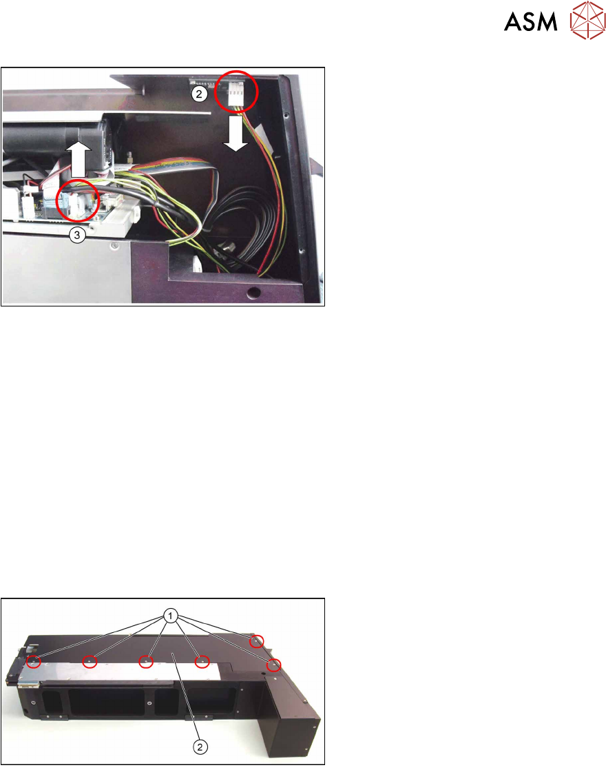
View from the left side, after opening the
side cover panel.
► Unplug the connector from the display
board connection(2).
► Unplug the connector(3) from the
connection for the LDU-X control
board.
Installation
Installation is performed by following the above instructions in the reverse order.
Both connectors have the same PIN arrangement which is why they both fit wither in the connec-
tion for the LDU-X control board or that for the display board.
► Plug one of the cable connectors into the connection marked on the display board.
► Plug the other cable connector into the connection marked on the LDU-X control board.
► Replace the two cable ties which you removed earlier on.
► Fit the left side cover into place (see section 4.2.29.10 "Fitting the Side Covers" [}65]).
4.2.29 Frequent Service Tasks
The steps described in this chapter are partial steps needed for service work. The service work to
be performed is indicated in these partial steps.
4.2.29.1 Removing the Side Covers
► Loosen the 6 screws (1) fastening the
left side cover(2) and then remove
the cover.
► Do the same for the right side cover.