00196062-03_SM_LDU-X_EN.pdf - 第37页
4 Service Work 4.2 Replacing Spare Parts Service Manual SIPLACE LDU-X Linear Dipping Unit 11/2017 37 4.2.15 Replacing the EMERGENCY STOP Button Overview Emergency stop switch [03062334-xx] 1. Cable to LDU-X controller 2.…
4 Service Work
4.2 Replacing Spare Parts
36 Service Manual SIPLACE LDU-X Linear Dipping Unit 11/2017
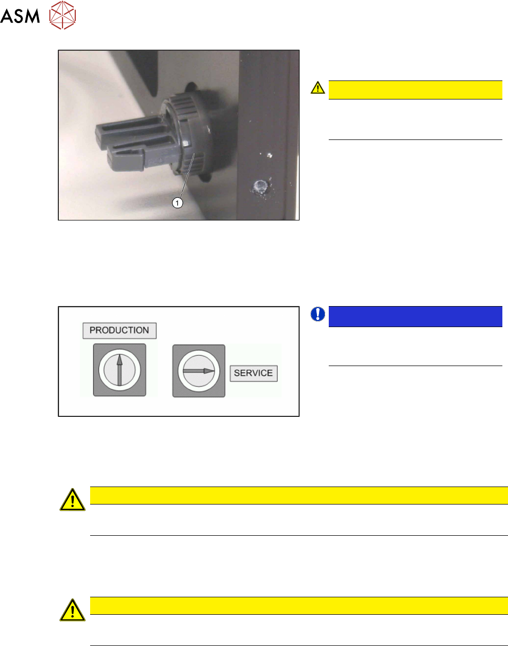
► Carefully unscrew the plastic nut(1)
from the switch.
CAUTION!
The plastic nut is very sensitive and
could easily break!
Avoid the use of pliers etc.
.
► Carefully pull the switch out of the
housing towards the front.
► Disconnect the switch cable from the main control board (see section 4.2.29.8 "LDU-X Con-
troller" [}62]). Note the colour and the exact position of the cable. You may need to use a
pair of tweezers to help you.
► Take the cable with the switch unit out of the LDU-X.
Installation
NOTICE!
When installing the switch make sure
that it is possible to adjust the two il-
lustrated switch positions.
.
► Insert the new switch. The seal must be inserted on the outside of the housing, between the
service switch and the housing panel.
► Place the plastic nut on the switch. However, do not tighten the nut completely, so that you
can still turn the switch.
CAUTION
The plastic nut is very sensitive and could easily break!
► Avoid the use of pliers etc.
► Plug in the switch unit.
► Turn the switch in such a way that the switch unit clip points downwards.
► Carefully tighten the nut per hand.
CAUTION
Important installation instructions
► Replace any opened cable ties with new ones.
► Further installation is performed by following the above instructions in the reverse order.
See also
2 4.2.19 "Replacing the Motor with Gearing and Encoder" [}41]
4 Service Work
4.2 Replacing Spare Parts
Service Manual SIPLACE LDU-X Linear Dipping Unit 11/2017 37
4.2.15 Replacing the EMERGENCY STOP Button
Overview
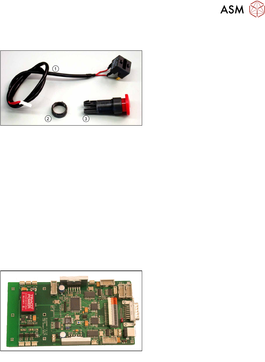
Emergency stop switch [03062334-xx]
1. Cable to LDU-X controller
2. Plastic nut
3. EMERGENCY STOP SWITCH
Equipment required
●
Standard tools
●
Allen key size 6
●
Cable tie
●
Spare part: emergency off switch [03062334-xx] (incl. switch unit with cable and plastic nut)
Removal / installation
The removal and installation of the emergency off switch follows the same procedure as that for the
service switch.
See also
2 4.2.14 "Replacing the Service Switch" [}34]
4.2.16 Replacing the LDU-X Controller
Overview
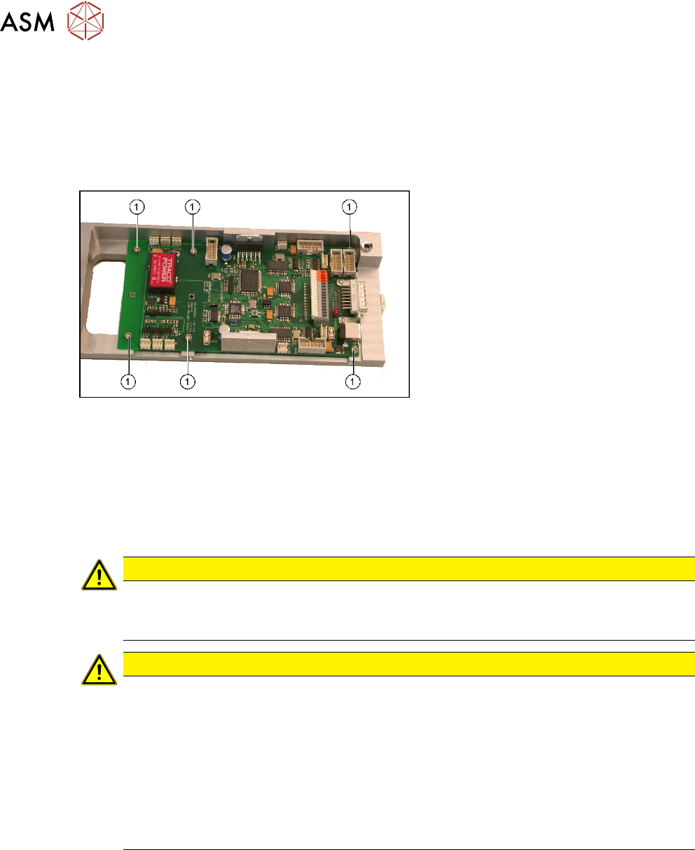
LDU-X control board [03062897-xx]
Equipment required
●
Standard tools
●
Allen key, sizes 5, 3 and 2.5
●
Spare part: LDU-X control board [03062897-xx]
4 Service Work
4.2 Replacing Spare Parts
38 Service Manual SIPLACE LDU-X Linear Dipping Unit 11/2017
Removal
► Remove the side covers (see 4.2.29.1 "Removing the Side Covers" [}57]).
► Dismantle the base unit.
► Divide the base unit into upper and lower parts.
► Unplug all connectors from the LDU-X controller (see 4.2.29.3 "Removing and Dismantling the
LDU Basis" [}58]).
► Loosen the 6 screws (1) fastening the
LDU-X control board and remove the
board.
Installation
► Installation is performed by following the above instructions in the reverse order.
► Restore the press-fit connections for the LDU-X control board.
► Fit the LDU base unit back together.
► Re-install the LDU base unit (see 4.2.29.9 "Assembling and Fitting the LDU Basis" [}63]).
► Fit the side covers (see 4.2.29.10 "Fitting the Side Covers" [}65]).
CAUTION
Important installation instructions
► Whenever you dismantle the base unit, you will need to level the LDU-X out again on
the machine (see operating instructions)!
CAUTION
Updating software
If the control board was replaced, you need to check whether the latest firmware version is
installed.
► Switch the LDU-X on.
► Go to the service menu to view the firmware version programmed.
► Check whether there is a more recent firmware version in the Software Download
Center (SDC) (www.siplace.com). You may want to download the new firmware from
the Software Download Center and transfer this to the control board.
If you have no access to the SDC, contact the SIPLACE hotline.
See also
2 4.2.19 "Replacing the Motor with Gearing and Encoder" [}41]