00196062-03_SM_LDU-X_EN.pdf - 第62页
4 Service Work 4.2 Replacing Spare Parts 62 Service Manual SIPLACE LDU-X Linear Dipping Unit 11/2017 4.2.29.8 LDU-X Controller Fig.4: LDU-X control board 1 3 pin connector strip for sensor (LLIM1) 2 From FS03 tray sens…
4 Service Work
4.2 Replacing Spare Parts
Service Manual SIPLACE LDU-X Linear Dipping Unit 11/2017 61
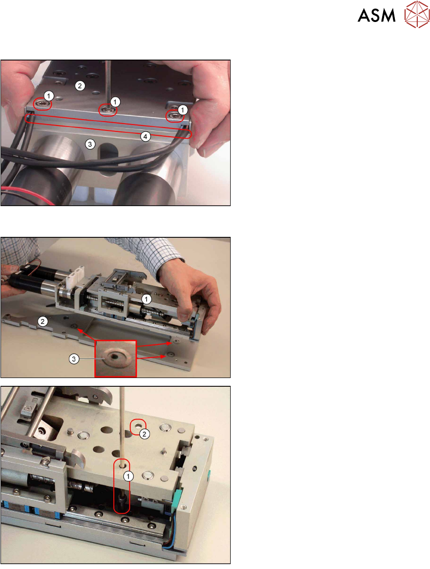
4.2.29.6 Fitting the Motor Mount
► Place the motor mount(3) onto the
upper section base plate(2) and
loosely tighten the 3 fastening
screws(1).
► Align the motor mount so that it is
straight and the edges(4) of the up-
per section base plate and the motor
mount are flush with one another.
► Tighten the 3 fastening screws(1).
Make sure that the edges remain
flush with one another.
4.2.29.7 Fitting the Base Plate
► Refit the upper section of the base
unit(1) on the base plate(2). Make
sure that the 3washers (0.3mm)(3)
are in the correct places.
► Loosely tighten the front two of the 3
fastening screws(1) and(2) for the
base plate of the base unit upper sec-
tion and the third fastening screw on
the back part of the motor couplings.
Make sure you do not move the 0.3
mm washers out of position.
► Align the upper section of the base
unit and the base plate so that they
are flush.
► Tighten the 3 fastening screws. Make
sure that the upper section of the
base unit and the base plate remain
flush with one another.
4 Service Work
4.2 Replacing Spare Parts
62 Service Manual SIPLACE LDU-X Linear Dipping Unit 11/2017
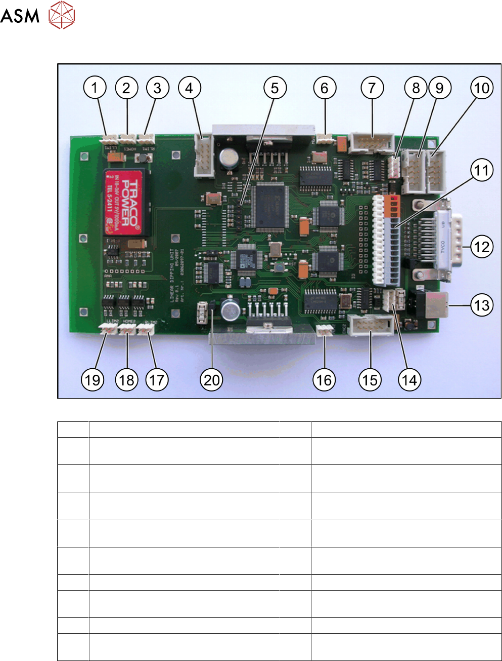
4.2.29.8 LDU-X Controller
Fig.4: LDU-X control board
1 3 pin connector strip for sensor (LLIM1) 2 From FS03 tray sensor
3 3 pin connector strip for sensor (RLIM1) 4 10 pin connector strip for refill unit
(MOT1)
5 6 pin connector pin strip for programming
interface
6 3 pin connector strip for motor, X axis
(MOT1)
7 10 pin connector strip for rotary encoder
from motor, X axis
8 4 pin connector strip for control board, X
adapter
9 10 pin connector strip for refill unit (op-
tional)
10 10 pin connector strip for service cable
(RS232)
11 16 pin terminal strip
(for details see table below)
12 Sub-D connector
13 USB socket 14 4 pin connector strip for display
15 10 pin connector strip for rotary encoder
from motor, X axis (MOT2)
16 3 pin connector strip for motor, X axis
(MOT2)
17 3 pin connector strip for sensor (RLIM2) 18 From FS03 dip plate sensor
19 3 pin connector strip for sensor (LLIM2) 20 2 pin connector strip for emergency stop
button

4 Service Work
4.2 Replacing Spare Parts
Service Manual SIPLACE LDU-X Linear Dipping Unit 11/2017 63
Description of terminal strip (11)
In the terminal strip diagram, terminal K1 is located at the top, terminal K16 is at the bottom.
K1 30V K9 -
K2 30V identification FS2 connection to K8 K10 -
K3 30V level sensor (+) brown K11 -
K4 30V key switch K12 Refill LED (+)
K5 Key switch K313 GND refill LED (-) blue
K6 Level sensor switch cable black K14 GND level sensor (-)
K7 - K15 GND
K8 Identification FS2 connection to K2 may
only be used with FS2
K16 GND
4.2.29.9 Assembling and Fitting the LDU Basis
► Place the lower section of the base
unit(2) and the LDU-X control
board(3) and the upper section of the
base unit(1) next to one another, as
shown in the diagram.
► Restore all press-fit connections in the
rear part of the LDU-X control board,
which points to the upper section.
NOTICE!
For an overview of the LDU-X con-
trol board press-fit connections,
refer to the previous section.
.
► Place the LDU housing(1) with the
other parts, as shown in the dia-
gram(2) and(3).
► Restore all press-fit connections
between the housing and the LDU-X
control board (service and emergency
stop button, display, control board X
adapter).