00196062-03_SM_LDU-X_EN.pdf - 第68页
4 Service Work 4.3 Adjustment 68 Service Manual SIPLACE LDU-X Linear Dipping Unit 11/2017 4.3 Adjustment When you loosen the couplings, you will need to remeasure the positions of the axes. 4.3.1 Setting the Zero Positio…
4 Service Work
4.2 Replacing Spare Parts
Service Manual SIPLACE LDU-X Linear Dipping Unit 11/2017 67
► Fix the two cables for the EDIF unit
with the cable clamp(1).
CAUTION!
Make sure that the cable has enough
play between the clamp and the
EDIF unit.
.
4.2.29.14 Fitting the Controller Cover
► Fasten the cover plate with 9 screws.
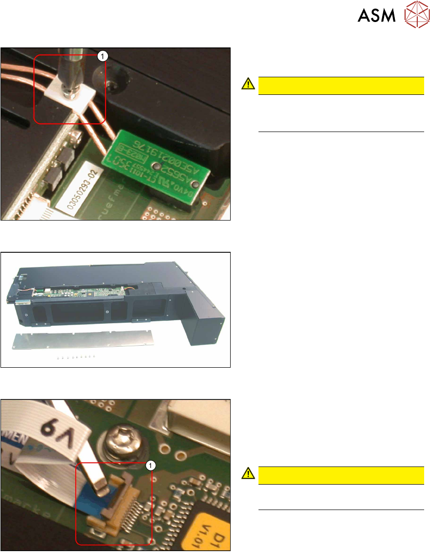
4.2.29.15 Removing the Cable to the IrDA Board
► Loosen the flat ribbon cable to the
IrDA board, by carefully lifting up the
clamp(1) e.g. with a flat-bladed
screwdriver.
► Take the flat ribbon cable out.
CAUTION!
Take care not to damage the cable or
clamp!
.
4 Service Work
4.3 Adjustment
68 Service Manual SIPLACE LDU-X Linear Dipping Unit 11/2017
4.3 Adjustment
When you loosen the couplings, you will need to remeasure the positions of the axes.
4.3.1 Setting the Zero Position of the X Axis
► Fit the dip plate and the park plate. Make sure that the plates are positioned correctly.
► Set the key switch on the LDU-X to the position SERVICE.
► SYST SETTINGS
► TEACH X-POSITIONS
► X TEACH ZERO POS
► Use the "+/-" buttons to set the zero position of the X axis.
NOTICE
The zero position of the X axis is set correctly when the front edge of the downholder is ap-
prox. 1 mm before the interface between the park and dip plate.
► Press the ENTER button.
NOTICE
When you open the menu again, the value is reset to 0!
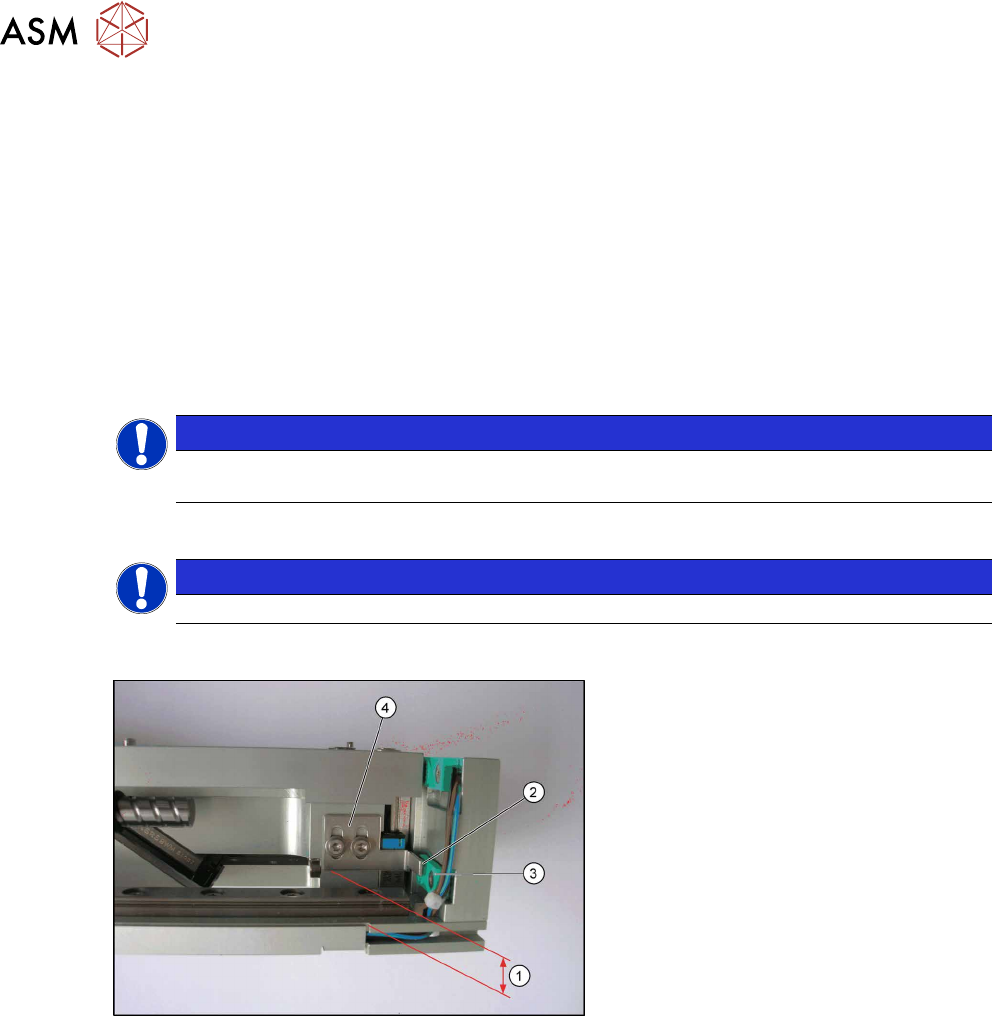
4.3.2 Setting the Z End Position Sensor
► Remove the cavity plate.
► Press the Z axis completely down.
► Adjust the Z axis switch flag (4), so
that there is a gap of 8.75mm (1)
between the cam and the base plate
(floor) or, from function state 3 on-
wards, a gap of 7.25mm.
Make sure that you have a small gap
(2) to the sensor (3) in the X direction.
The cam should slide by as near as
possible to the sensor, without touch-
ing it.
Sensor functions
When you select the relevant menu, the motors are shut off. This means that all axes can be
moved manually. If the sensor is approached, it will be shown as "on" in the menu. After the X and
Y sensor reaches its "on" state, there should still be at least 0.70 mm to the mechanical stop.
Z axis switch flag
Before you switch on for the first time, the cam needs to be fitted right at the bottom, so that the
LDU can initialize. After this, set the cam so that the sensor for the BERO Y BELOW triggers when
the table is 1.20 to 1.30 mm below the zero position. From this position, there should still be at
least 0.70 mm to the bottom mechanical stop. The zero position is the height at which the dip plate
is level with the park plate.
Dip plate sensor
The BERO DIP PLATE sensor must trigger at the latest 0.80 mm below the zero position.
Dip tray sensor
The BERO TRAY must correctly show the presence of the dip tray.

4 Service Work
4.4 Importing the LDU-X Firmware
Service Manual SIPLACE LDU-X Linear Dipping Unit 11/2017 69
Level sensor option
After fitting the level sensor, you need to determine the control position. This is the position at
which the tapered part of the tub is in the light beam. To do this, open the LEVEL SENSOR AD-
JUSTMENT function. The squeegee will automatically move forwards, until the position is found.
The value will then be saved.
Refill unit option
When the plunger is pushed upwards, the BERO CARTRIDGE sensor should change to "on".
When the belt drive is turned, the BERO DECODER sensor should alternate between "on" and
"off".
4.3.3 Setting the Zero Position of the Z Axis
► Fit the dip plate and the park plate. Make sure that the plates are positioned correctly.
► Set the key switch on the LDU-X to the position SERVICE.
► SYST SETTINGS
► TEACH Z POSITIONS
► Z TEACH ZERO POS
► Use the "+/-" buttons to set the zero position of the Z axis.
NOTICE
The zero position of the Z axis is set correctly when you can no longer feel the interface
between the park and dip plate with your finger.
► Press the ENTER button.
NOTICE
When you open the menu again, the value is reset to 0!
4.4 Importing the LDU-X Firmware
The following section describes how to transfer the LDU-X firmware to an LDU-X device. The firm-
ware is the LDU-X operating system.
NOTICE
This task should only be performed by SIPLACE service technicians.
Introduction
To import a new firmware version into the LDU-X, you need the following:
●
PC with Windows as operating system (2000, XP)
●
Software for the data transfer (download software)
WSD = Windows Serial Downloader
●
The new LDU-X firmware (hex file)
●
Cable for data transfer (service cable)
The download software is installed on a suitable PC and started. The LDU-X firmware is also saved
on this PC. The PC is connected to the LDU-X control board via a cable. The download software
sends the new LDU-X firmware via the serial port of the PC to the LDU-X processor, where it is
saved. The LDU-X memory is divided into a part needed for the program (running, displaying, lan-
guages etc.) and a part needed for the application data (speeds, end positions etc.).