00196062-03_SM_LDU-X_EN.pdf - 第43页
4 Service Work 4.2 Replacing Spare Parts Service Manual SIPLACE LDU-X Linear Dipping Unit 11/2017 43 ► Loosely screw the motor into place with the 4 screws and washers. Take care to align the motor properly. To do this, …
4 Service Work
4.2 Replacing Spare Parts
42 Service Manual SIPLACE LDU-X Linear Dipping Unit 11/2017
Removal
► Remove the side covers (see 4.2.29.1 "Removing the Side Covers" [}57]).
► Remove and dismantle the base unit, separating it into top and bottom sections and unplug all
press-fit connections to the LDU-X control board (see 4.2.29.3 "Removing and Dismantling the
LDU Basis" [}58]).
► Dismantle the base plate of the upper section of the base unit (see 4.2.29.4 "Removing the
Base Plate" [}60]).
► Dismantle the motor mounting plate (see 4.2.29.5 "Removing the Motor Mount" [}60]).
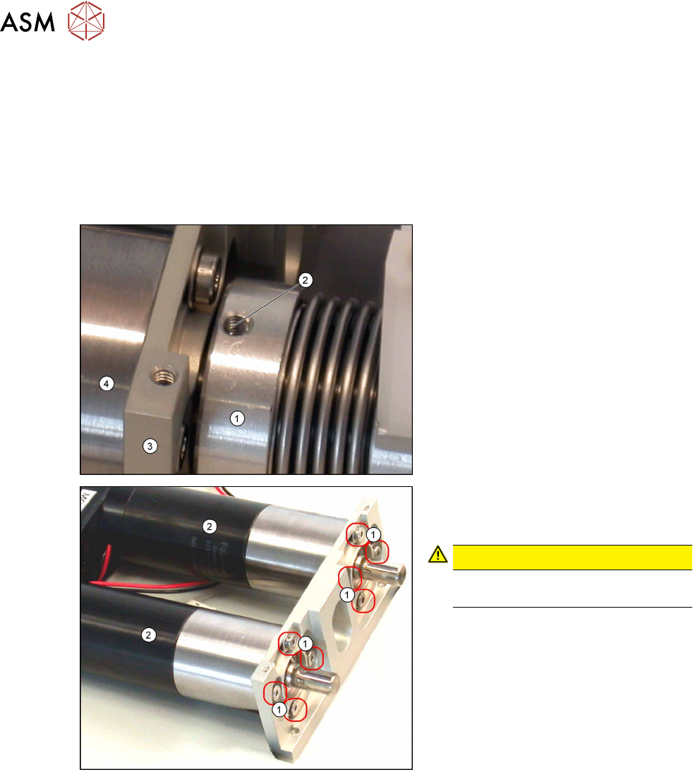
► On both couplings (1), loosen the two
grub screws (2) which face the motor
mount (3) and the motor (4) itself.
Do not unscrew the grub screws com-
pletely out of the thread if possible.
► Loosen the 4 screws (1) fastening the
defective motor (2) and take it out of
the motor mount.
CAUTION!
Make sure that you do not lose the
washers.
.
Installation
► Installation is performed by following the above instructions in the reverse order. To do so,
proceed as follows:
4 Service Work
4.2 Replacing Spare Parts
Service Manual SIPLACE LDU-X Linear Dipping Unit 11/2017 43
► Loosely screw the motor into place
with the 4 screws and washers. Take
care to align the motor properly. To do
this, make sure that the rectangular
part of the housing at the rear of the
motor, on the right-hand side, points
inwards.
► Once the motor has been correctly
aligned, tighten the 4 screws. Make
sure that the alignment is not changed
while you tighten the screws.
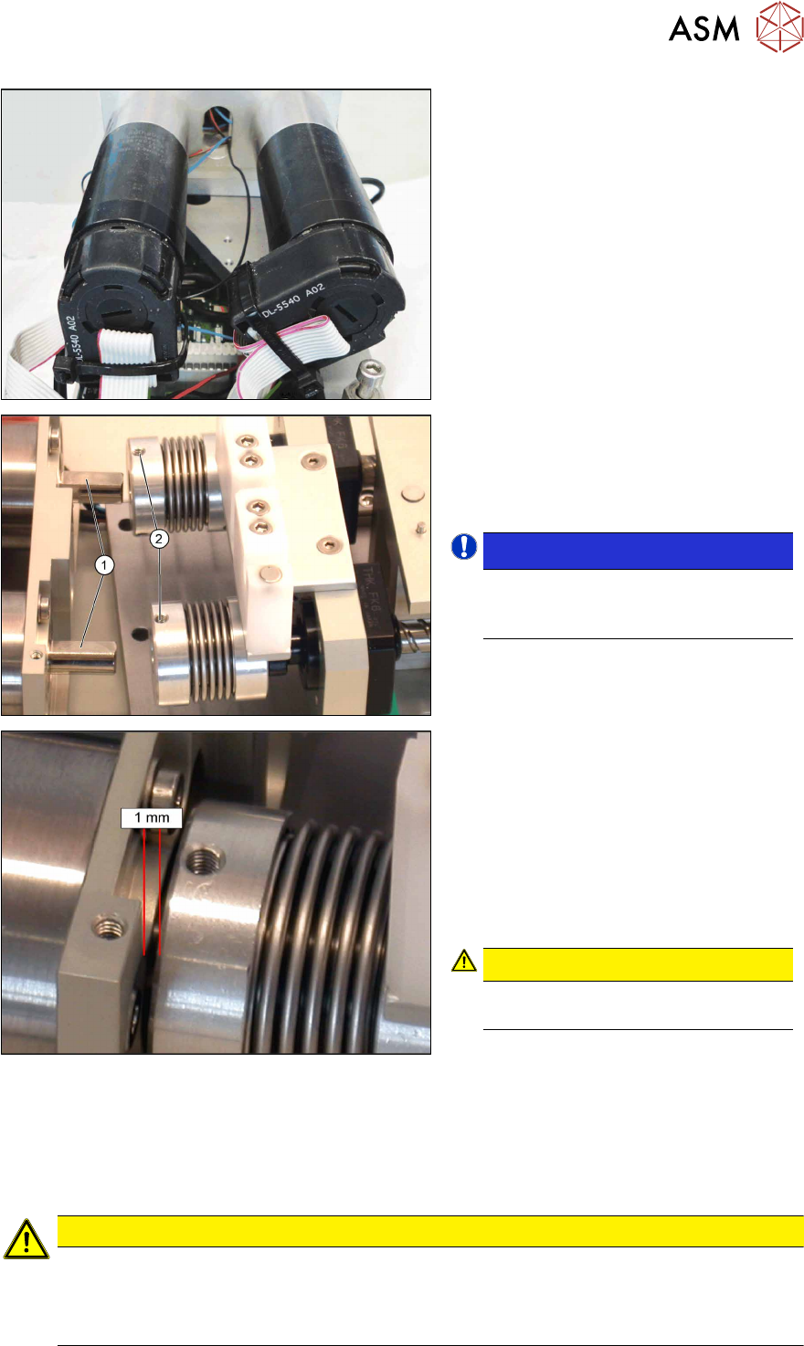
► Before assembly, align the motors
and couplings so that the flattened
side of the motor shafts (1) and one of
the two grub screws (2) for the coup-
ling point upwards.
NOTICE!
A reliable connection is only formed if
one of the grub screws touches the
flattened side of the motor shaft!
.
► Carefully push the motor shafts into
the couplings.
► Align the motors and couplings so that
there is a gap of around 1 mm
between the couplings and the motor
mount.
► Tighten the grub screws. Make sure
that the set gap does not change dur-
ing tightening.
CAUTION!
Make sure that the coupling does not
grate against the motor mount!
.
► Refit the motor fixing plate (see4.2.29.6 "Fitting the Motor Mount" [}61]).
► Refit the base plate (see 4.2.29.7 "Fitting the Base Plate" [}61]).
► Restore the press-fit connections for the LDU-X control board, reassemble and refit the LDU
base (see 4.2.29.9 "Assembling and Fitting the LDU Basis" [}63]).
► Fit the side covers (see 4.2.29.10 "Fitting the Side Covers" [}65]).
CAUTION
► Whenever you loosen the couplings, you will need to remeasure the positions of the
axes.
► Whenever you dismantle the base unit, you will need to level the LDU-X out again on
the machine (see operating instructions)!
4 Service Work
4.2 Replacing Spare Parts
44 Service Manual SIPLACE LDU-X Linear Dipping Unit 11/2017
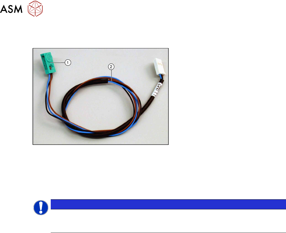
4.2.20 Replacing the proximity switch
Overview
Proximity switch assembly [03068930-xx]
1. Proximity switch
2. Cable to LDU-X controller
Equipment required
●
Standard tools
●
Allen key, sizes 5, 3 , 2 and 1.3
●
Spare part: proximity switch assembly [03068930-xx] with 4 adhesive labels
NOTICE
Adhesive label
There is only one model that is used for all 4 proximity switches in the LDU-X. The switch
can be clearly marked with the labels provided.
Removal
► Remove the side covers (see 4.2.29.1 "Removing the Side Covers" [}57]).
► Remove and dismantle the base unit, separating it into top and bottom sections and unplug all
press-fit connections to the LDU-X control board (see 4.2.29.3 "Removing and Dismantling the
LDU Basis" [}58]).
► Dismantle the base plate of the upper section of the base unit (see 4.2.29.4 "Removing the
Base Plate" [}60]).