COU2000 PRO计数器英文说明书 Operaton Manual-en(1).pdf - 第20页
VERSION: .1.01 E 20 / 52 4.2.2.3 Ampl ifier for FX-501-C2 4.2.2.3.1 Part descriptio n: 4.2.2.3.2 Th reshold value of the ampli fier The threshold value i s ver y import ant, this value represent th e difference of 2 stat…
VERSION: .1.01 E
19 / 52
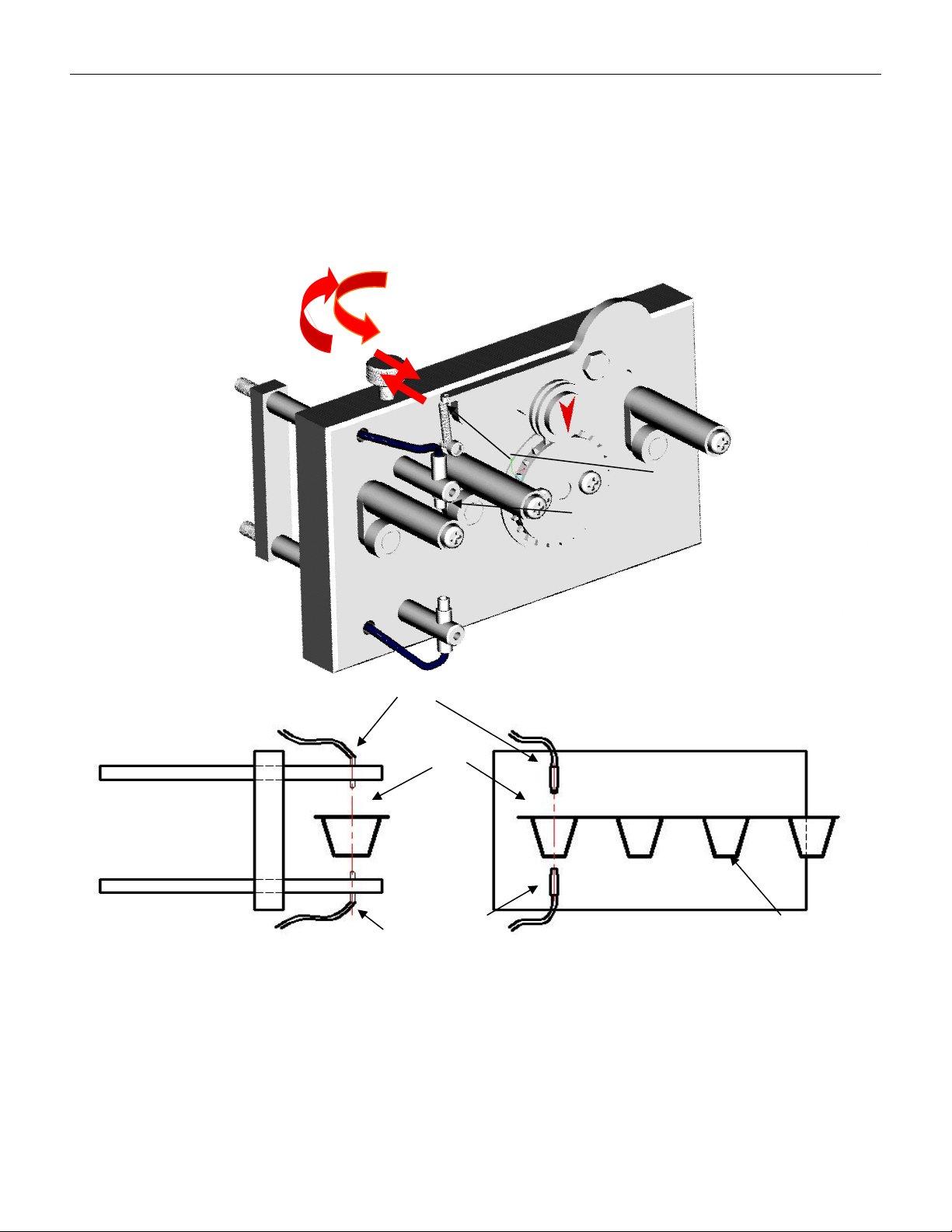
Receive end
Transmitter end
Transmitter
end
Tape
Groove
Receiver end
Loose
Tighten
4.2.2.2 Fiber optic alignment mechanism
To activate the empty material detection function for different widths of material strips, the
fiber optic alignment mechanism must be relaxed first to align the fiber optic emitting end
with the center hole of the part slot on the material strip (i.e. D1 in Figure 3-1), and then
locked.
VERSION: .1.01 E
20 / 52
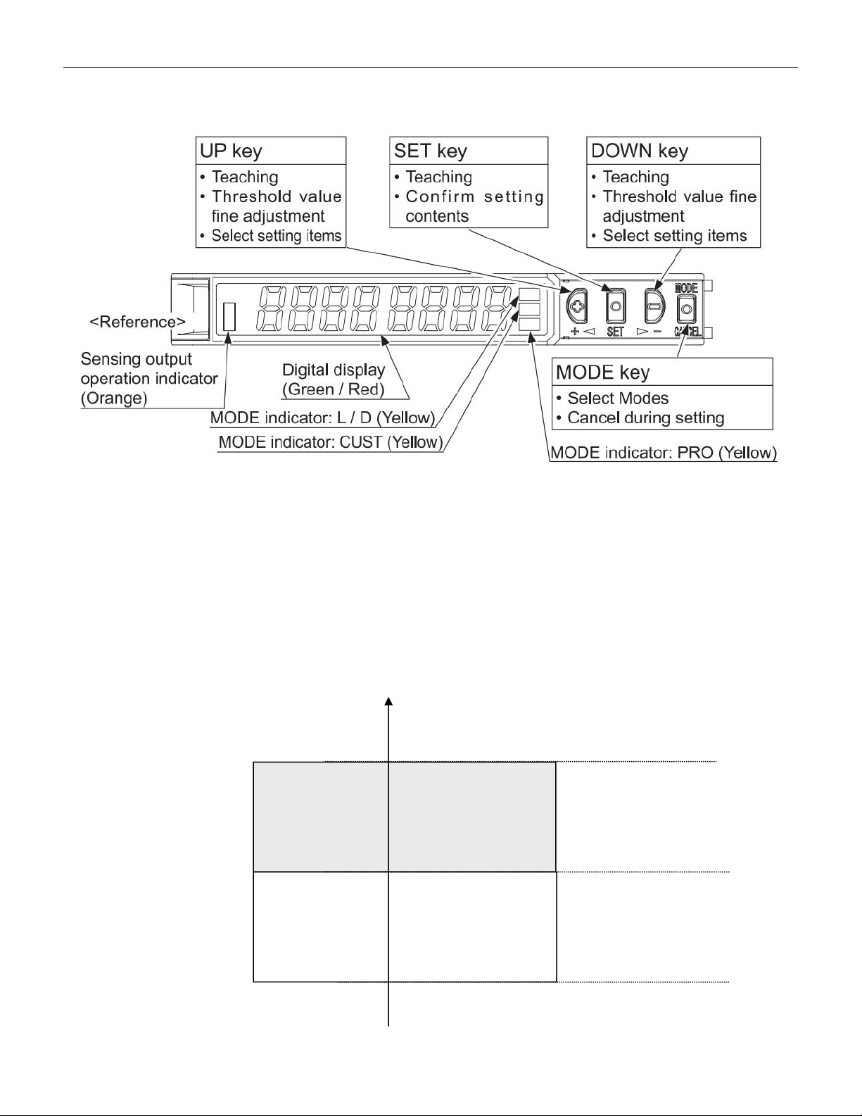
4.2.2.3 Amplifier for FX-501-C2
4.2.2.3.1 Part description:
4.2.2.3.2 Threshold value of the amplifier
The threshold value is very important, this value represent the difference of 2 status, with
and without components. When using pocket check function, we need to set this
threshold value. Once the light input exceeds the threshold value, the amplifier will
determine that there are missing parts in the material strip. As shown in the figure below:
Threshold
value
With component
No component
Light
sensing
ON
OFF
VERSION: .1.01 E
21 / 52
4.2.3 Advanced setting of the amplifier
Please see the instruction manual for FX-501(FX-551) for more detailed
setting
4.2.4 Instructions for Pocket check function
4.2.4.1 Please refer to the section on basic operations in section 4.1 to activate the empty
material detection function by pressing Pocket check.
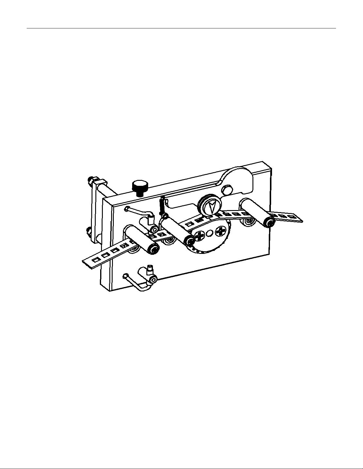
4.2.4.2 Please refer to the section on basic operations in 4.1 to perform operations such as
resetting, setting pitch, preset values, etc. As shown in the figure below, the material strip
passes through the upper and lower guide columns and penetrates into the material strip
(as shown in the figure below)。
The material strip passes through between the upper and lower guide columns
4.2.4.3 Adjust the fiber alignment mechanism to align the fiber with the center of the
component slot in the material strip,
4.2.4.4 Setting of threshold values
Drag the carrier tape to align the emitting end of the optical fiber with the center of the
slot that there is no component, press the SET button once, and the light input amount on
the display screen will flash for about 1 second before returning to the current value, while
the TEACH yellow cursor will continue to flash. Drag the tape again to align the emitting
end of the optical fiber with the center of the slot that there is componen, and press the SET