DEK INFINITY USER MANUAL.pdf.pdf - 第170页
INFINITY ',$*126 7,&6 6<67(0 5.2 User Manual Software Version 7 SYSTEM Selecting this diagnostic module opens the following window: The menu bar changes displaying the following: Next / Previous keys move the…
INFINITY
',$*1267,&6
,1752'8&7,21
Software Version 7 User Manual 5.1
CHAPTER 5 DIAGNOSTICS
INTRODUCTION The diagnostic function is an aid to the user to allow individual access and
control of motors and modules. It allows the user to control the sequence of the
machine so that a particular module can be exercised.
To enter the diagnostic mode press the Maint button.
The menu bar changes displaying the Diagnostic option.
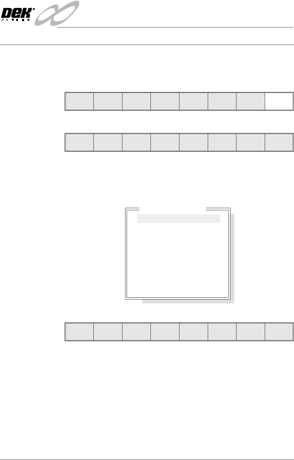
Press the Diagnost (F6) button. If a password exists a window displays the
message ‘Diagnostic Password’. If the password is incorrect control displays
the message‘Invalid password entered’ and returns to the previous menu. If
the correct password is entered or no password exists a pop up window displays
the following:
The menu bar changes displaying the following:
Next / Previous keys move the highlight bar up and down the list of diagnostic
modules.
Select Module key opens a new window displaying the diagnostic functions
available for the selected module.
Exit returns operation to the start of initialization.
NOTE
Before any diagnostic function is used in any of the modules they must be homed
first or they are not able to initiate a command.
Run Head
Paste
Load
Clean
Screen
Adjust Setup Monitor Maint.
Calibrat
Pressure
Calibrat
Offset
Calibrat
Vision
House
Keeping
Set
Prefs
Diagnost
Tes t
Cycles
Exit
Module Diagnostic Page
System
Print Head
Print Carriage
ProFlow / Squeegee
Camera Axes
Rail System
Paste Dispense System
Screen Alignment
Screen Change
Screen Cleaner
Rising Table
MIU
Autoflex Tooling
Select
Module
Next Previous Exit
INFINITY
',$*1267,&6
6<67(0
5.2 User Manual Software Version 7
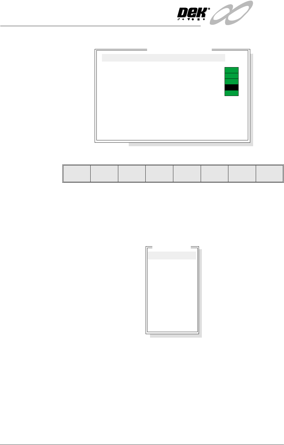
SYSTEM Selecting this diagnostic module opens the following window:
The menu bar changes displaying the following:
Next / Previous keys move the highlight bar up and down the list of selectable
diagnostic functions.
Run Diagnost activates the diagnostic function, as selected by the highlight bar.
Exit returns operation to the module diagnostic page.
Display All Digital
Inputs
Selecting this diagnostic function opens the following window:
System Diagnostics
ON
ON
ON
ON
OFF
Display all Digital Inputs
Display all Analogue Inputs
Toggle Red Beacon
Toggle Amber Beacon
Toggle Green Beacon
Toggle Lid Bolt
Data Logging
Change Edit Password
Change Diagnostics Password
Change Terminate Password
Change Adjust Password
Change Fiducial Set-Up Password
Change Maintenance Password
Terminate Control Program
Run
Diagnost
Next Previous Exit
Digital Group
NM 1 Group 0
NM 1 Group 1
NM 1 Group 2
NM 1 Group 3
NM 1 Group 4
MMOV 1 Group 0
MMOV 1 Group 1
MMOV 1 Group 2
MMOV 1 Group 3
MMOV 2 Group 0
MMOV 2 Group 1
MMOV 2 Group 2
MMOV 2 Group 3
INFINITY
',$*1267,&6
6<67(0
Software Version 7 User Manual 5.3
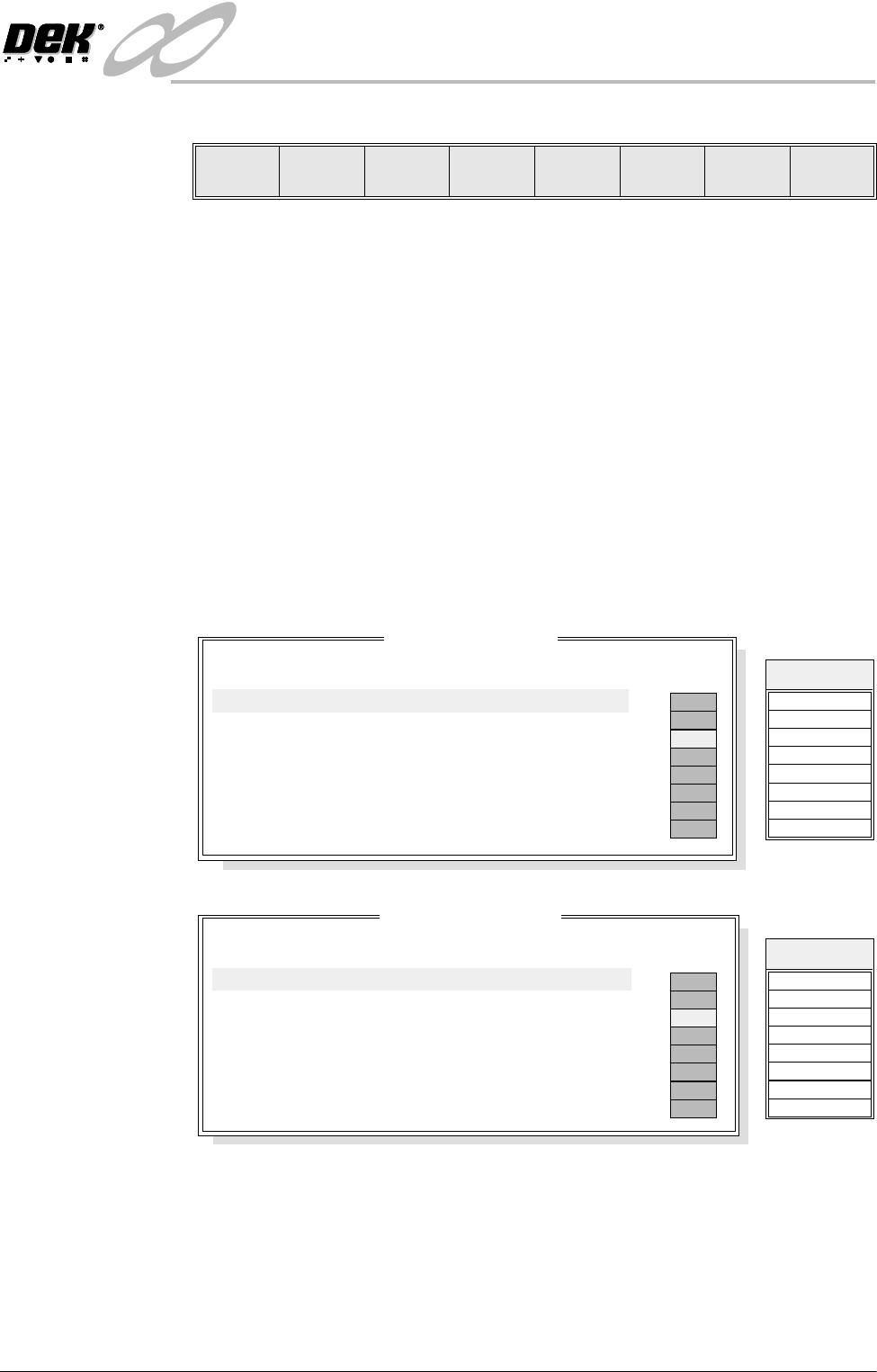
The menu bar changes displaying the following:
Next / Previous keys move the highlight bar up and down the list of diagnostic
modules.
Select key opens a new window displaying the diagnostic functions available
for the selected option.
Exit returns operation to the system diagnostics page.
NM1 is a NextMove I/O card that is housed in the PC. The MMOV1, MMOV2
and MMOV 3 are MultiMove I/O cards that are housed in the machine controller
enclosure. The NextMove and MultiMove cards monitor and control various
drives and control cards in the machine controller enclosure.
NOTE
The signal listings, shown on the right hand side of the following diagnostic
windows, are not shown on the MMI screen, they are included here as an aid to
show the relationship between the I/O signal and the point description.
NM1 Group 0
NM1 Group 1
Select Next Previous Exit
NM 1 Group 0
Point Description
---------------------
---------
-------
-----------
------
Bit No
Sense
Direction
State
OFF
ON
OFF
OFF
OFF
OFF
OFF
OFF
Table HOME
Table LIMIT
Table at Home
Rail Lifted Left
Rail Lifted Right
Camera X HOME
Print Carriage HOME
Servo Amp error
0
1
2
3
4
5
6
7
Positive
Positive
Negative
Negative
Negative
Positive
Positive
Positive
Input
Input
Input
Input
Input
Input
Input
Input
DIGIN0
DIG IN 4
DIG IN 1
Signal
DIGIN5
DIGIN6
DIGIN2
DIGIN3
DIGIN7
NM 1 Group 1
Point Description
---------------------
---------
-------
-----------
------
Bit No
Sense
Direction
State
X Rear INDEX
X Rear HOME
X Forward INDEX
X Forward HOME
YActuator INDEX
YActuator HOME
MUX HOME
Camera Y HOME
0
1
2
3
4
5
6
7
Positive
Positive
Positive
Positive
Positive
Positive
Positive
Positive
Input
Input
Input
Input
Input
Input
Input
Input
OFF
ON
OFF
OFF
OFF
OFF
OFF
OFF
DIGIN8
DIG IN 12
DIG IN 9
Signal
DIGIN13
DIGIN14
DIGIN10
DIGIN11
DIGIN15