DEK INFINITY USER MANUAL.pdf.pdf - 第270页
INFINIT Y ',163(&7,21 ',163(&7,21 6(78 3 8.30 User Manual Software Versi on 7 6. Select Adjust Site . The learn site para meters window is displayed. 7. Adjust site parameters as required using Nex…
INFINITY
',163(&7,21
',163(&7,216(783
Software Version 7 User Manual 8.29
Auto Learn Prior to carrying out auto learn, the 2Di setup described in the preceding pages
must have been carried out. To successfully auto learn, the site setup should be
the base site of the device, (Figure 8-2 Auto Learn Site Types refers).
1. Select Auto Learn.
The message ‘Select Component type to Auto Learn:’ is displayed. The
following messages appear beneath this message in rotation.
Row - Start at left most end of horizontal
Column - Start at topmost end of vertical
QFP - (Quad Flat Pack) - Start at left most end at top of left horizontal
line
BGA - (Ball Grid Array) - Start at top left corner of array
2. Select the required component to learn.
The message bar reports the progress of the auto learn as a set of sites of the
appropriate type are created and learnt. The original site, and each site that
is created, is given the same name as the original site, but with a ‘~’ symbol
followed by a three digit number in sequence.
As each new site is created and learnt, the newly created name and data is
displayed in the Edit Site Parameters window.
NOTE
During Auto Learn, if any creating or learning sequence fails, the message
‘Adjust Site. ..........’ appears with an explanation the user is given the
opportunity to recover the sequence or abort the operation.
3. On completion of a successful auto learn of the selected component, the
following menu bar is displayed:
4. Repeat Steps from Site Setup for further auto learn features.
5. If feature not completely learnt, the following menu bar is displayed:
Learn
Board
Adjust
Screen
Auto
Learn
Next Previous Incr. Decr. Exit
Learn
Row
Learn
Col
Learn
QFP
Learn
BGA
Learn
BGAframe
Exit
Edit
Global
Edit
Limits
Delete
Site
Edit
Site
Inspect
Site
Exit
Adjust
Site
Learn
Board
Learn
Screen
Continue Exit
INFINIT
Y
',163(&7,21
',163(&7,216(783
8.30 User Manual Software Version 7
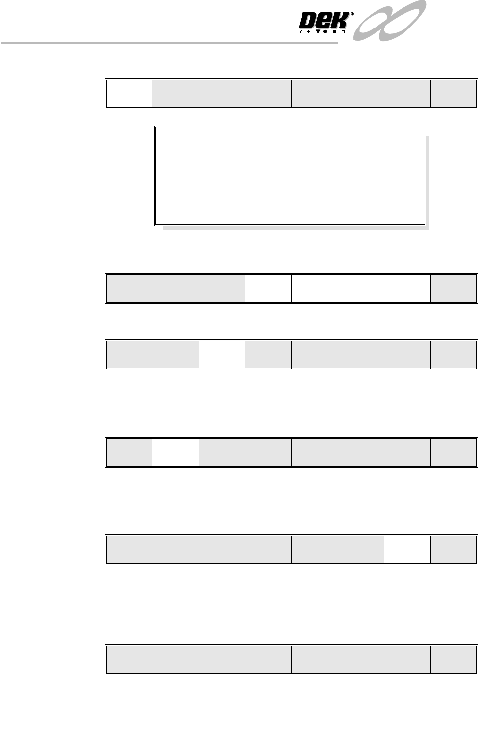
6. Select Adjust Site. The learn site parameters window is displayed.
7. Adjust site parameters as required using Next, Previous, Incr. and Decr.
keys.
8. Select Learn Screen.
9. The message ‘Screen Learnt’ is displayed. If message ‘....Screen Not
Learnt’ is displayed, edit the site parameters and select Learn Screen.
10.Select Learn Board.
11. The message ‘Board Learnt’ is displayed. If message ....‘Board Not
Learnt’ is displayed, edit the site parameters and select Learn Board.
12.Select Continue. The auto learn process continues.
The message bar reports the progress of the auto learn as the system searches
for a site, learns a site and moves to the next site.
13.On completion of a successful auto learn of the selected component, the
following menu bar is displayed:
14.Carry out Section Inspect for all sites.
Adjust
Site
Learn
Board
Learn
Screen
Continue Exit
SITE X COORD
SITE Y COORD
SITE WIDTH
SITE HEIGHT
SCREEN GRAPHIC X
SCREEN GRAPHIC Y
BOARD GRAPHIC X
BOARD GRAPHIC Y
52.0
36.5
2.00
2.00
-0.01
-0.01
0.00
0.00
mm
mm
mm
mm
mm
mm
mm
mm
Learn Site Parameters
Continue
Learn
Board
Learn
Screen
Next Previous Incr. Decr.
Continue
Learn
Board
Learn
Screen
Next Previous Incr. Decr. Exit
Adjust
Site
Learn
Board
Learn
Screen
Continue Exit
Adjust
Site
Learn
Board
Learn
Screen
Continue Exit
Edit
Global
Edit
Limits
Delete
Site
Edit
Site
Inspect
Site
Exit
INFINITY
',163(&7,21
',163(&7,216(783
Software Version 7 User Manual 8.31
Inspect 1. Select Exit.
2. Select Step until board is printed.
3. Select Step until the Inspect Setup menu button is displayed.
4. Select Inspect Setup.
5. Select Inspect Site.
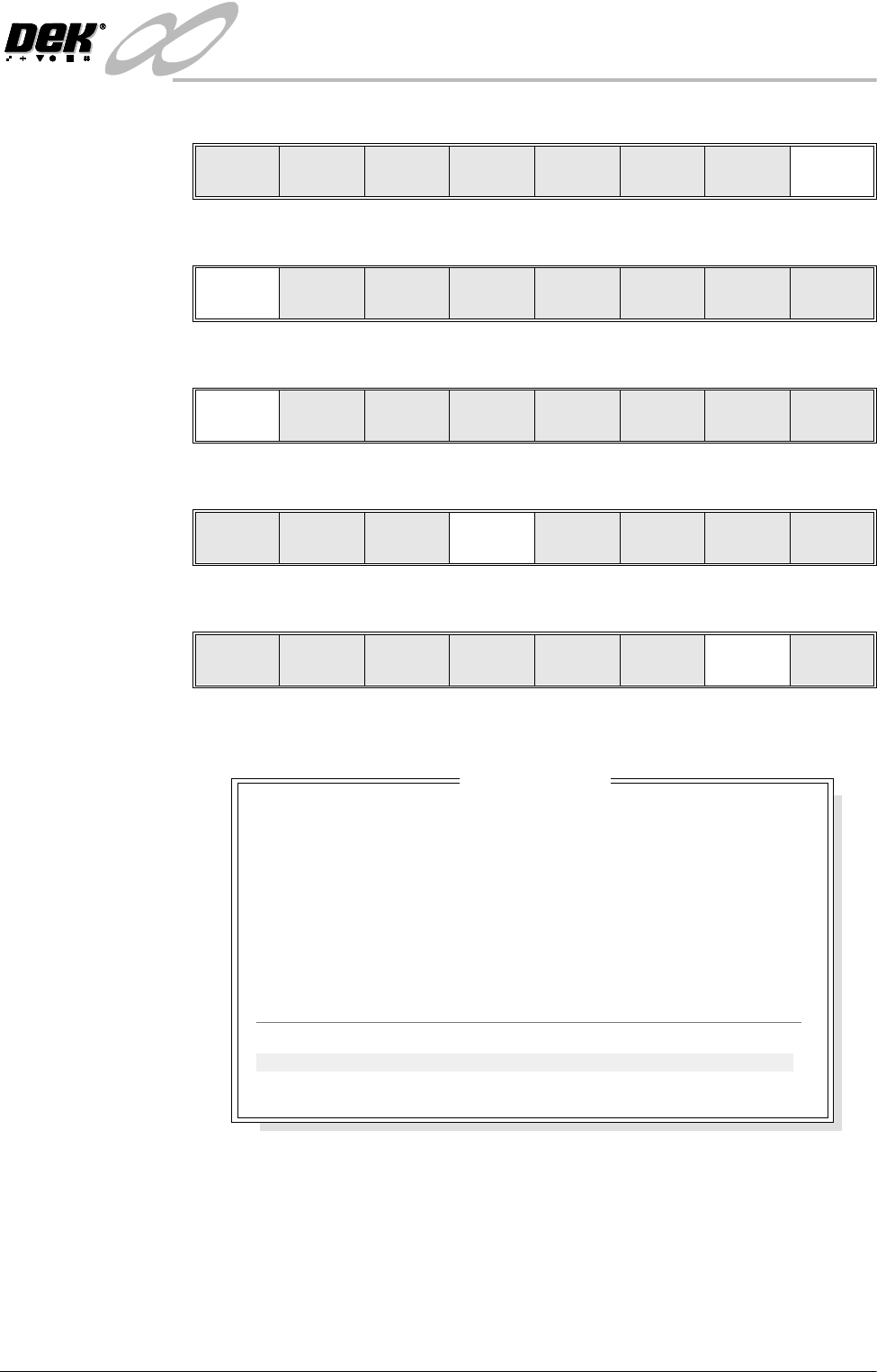
The following window is displayed:
NOTE
A reliable paste present reading is made only when the lighting is set
correctly.
6. If the board inspection type is set to advanced carry out Steps 6a and 6b. If
the board inspection type is set to none or basic carry out Step 6c.
Edit
Global
Edit
Limits
Delete
Site
Next
Site
Previous
Site
Edit
Site
Inspect
Site
Exit
Step
Inspect
Setup
Single Exit
Step Single Exit
Step
Inspect
Setup
Single Exit
Edit
Global
Edit
Limits
Delete
Site
Next
Site
Previous
Site
Edit
Site
Inspect
Site
Exit
SITE NAME
Maximum Blockage
Smear Area
Minimum Paste
X Alignment
YAlignment
Bridging
Minimum Paste Volume
Bridge Warnings
Bridge Alarms
SITE 1
0%
0.00 sq mm
94%
+0.007mm
-0.003mm
5.012mm
93%
0
0
Inspection Results
PASS
PASS
PASS
PASS
PASS
PASS
PASS
No. Blockage Paste Present Volume AlignX AlignY
1 0% 94% 93% +0.007 -0.003
2 0% 98% 97% +0.006 -0.002