DEK INFINITY USER MANUAL.pdf.pdf - 第249页
INFINITY ',163(& 7,21 02'8/( 29(59,(: Soft ware Ver sion 7 User Manual 8.9 Image Recording Selecting Save Image saves the inspection object data using the save object command. This option is only availab…
INFINIT
Y
',163(&7,21
02'8/(29(59,(:
8.8 User Manual Software Version 7
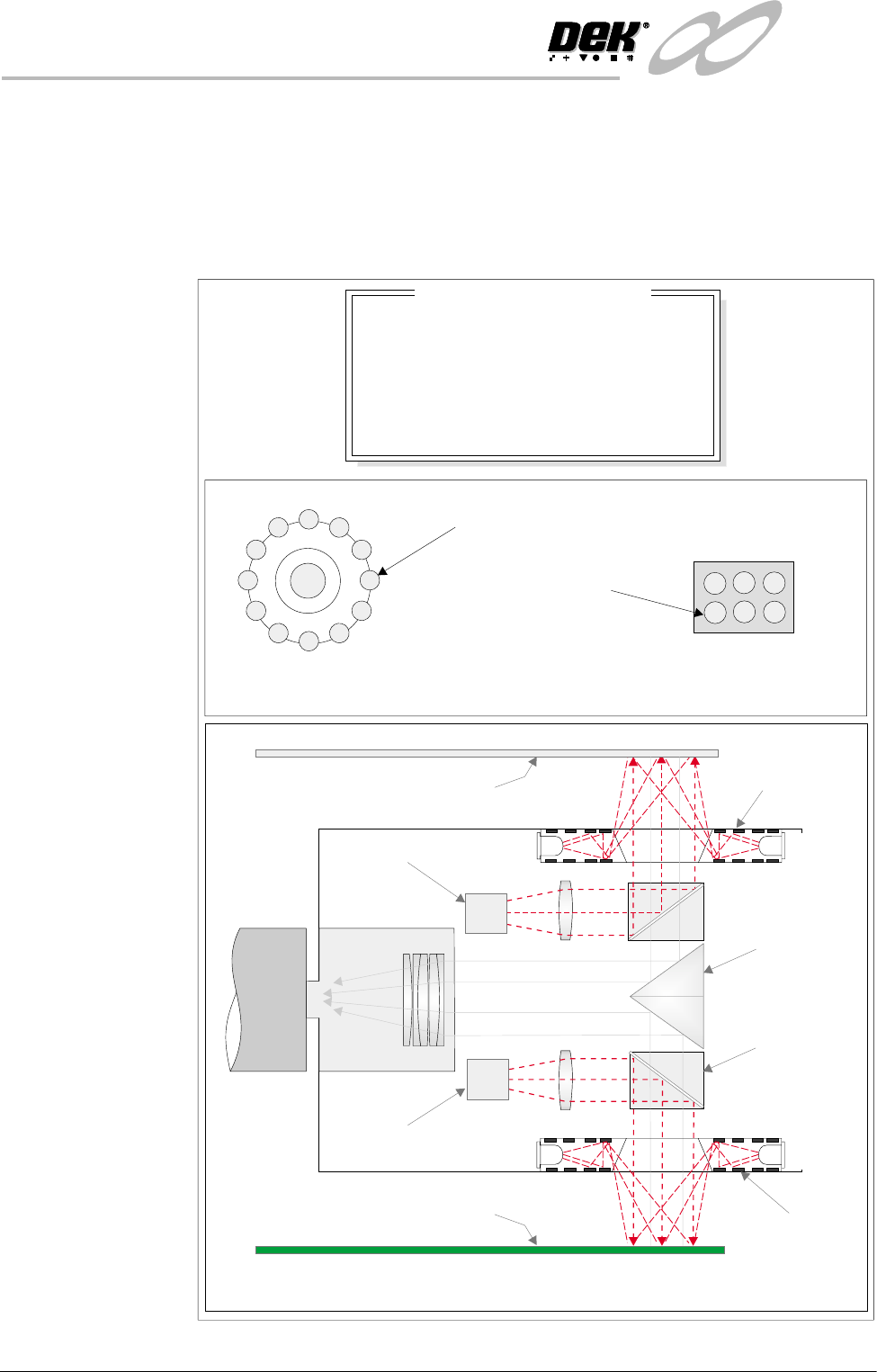
Lighting The lighting levels for 2D inspection is software controlled. For a more detailed
description of the camera and optical unit refer to the Technical Reference
Manual, Camera and Vision Systems Module Chapter.
The green camera lighting parameters and functions are shown below. Each
lighting group can be set by the operator to a level between 0 to 15, where 15 is
the brightest.
Figure 8-4 Software Controlled Lighting - Green Camera
Oblique Lighting LED
Board and Stencil Lighting LED Configurations
Adjustable iIlumination of Board and Stencil
Direct Lighting LED
Plan ViewPlan View
8
8
8
8
-1.0
-1.5
2.0
2.0
Inspection Lighting Parameters
Screen Vertical
Screen Oblique
Board Vertical
Board Oblique
Window Left
Window Top
Window Width
Window Height
mm
mm
mm
mm
Underside Stencil
Board
Prism
Beam Splitter
Cube
Oblique
Lighting
Oblique
Lighting
Direct Lighting
Direct Lighting
Camera
INFINITY
',163(&7,21
02'8/(29(59,(:
Software Version 7 User Manual 8.9
Image Recording Selecting Save Image saves the inspection object data using the save object
command. This option is only available if image recording in set preferences
is set to VP or PC disk.
It is recommended to use PC disk only for image recording. When saved the file
name is inspnnnn.im2, where n is an incrementing number.
The first image saved after initialization is insp0001.im2.
NOTE
VP disk saves to the Vision HD if fitted.
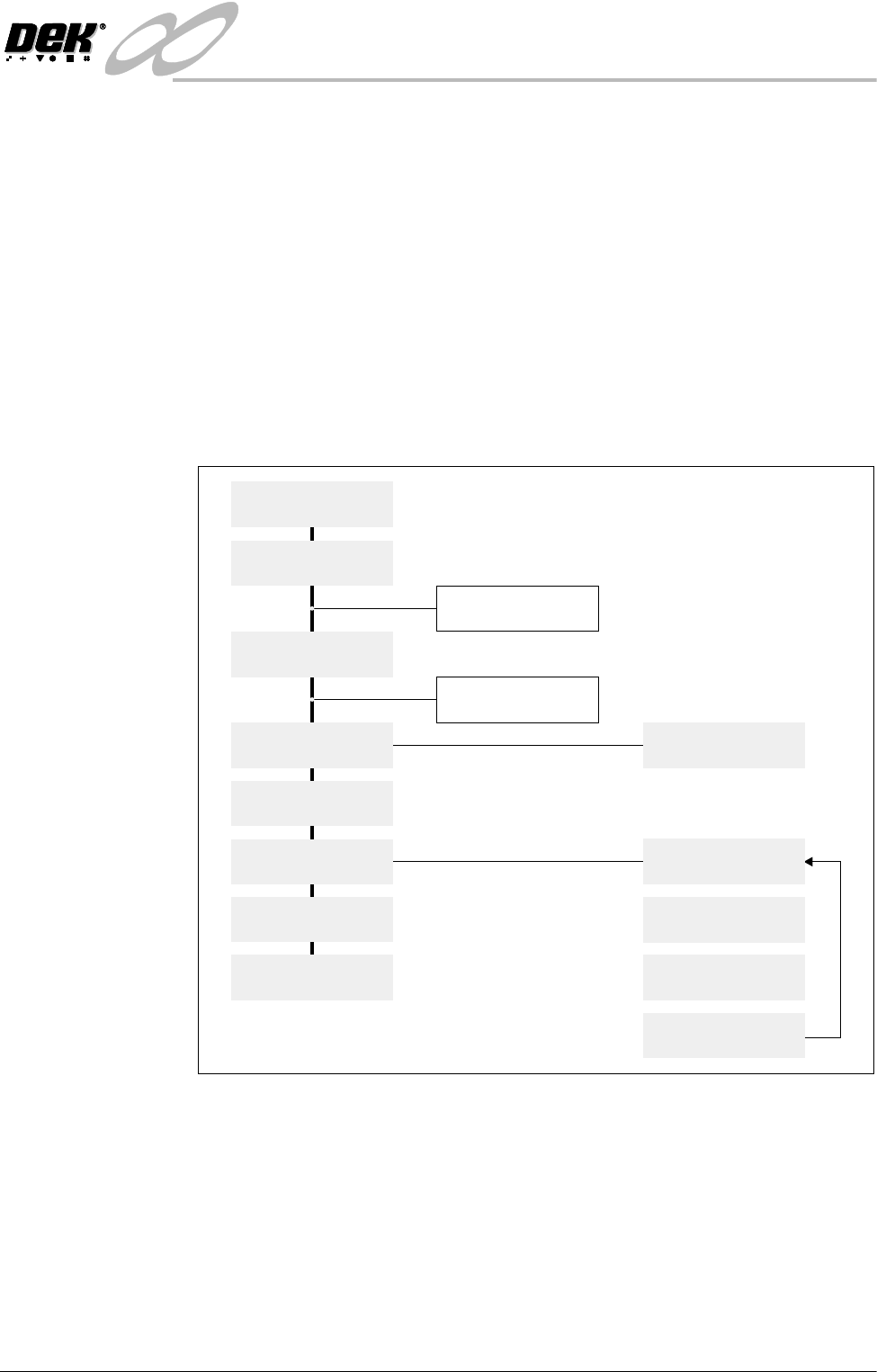
Inspection Setup Correct inspection setup is the key to effective inspection. By following the
steps of the setup sequence, shown in the summary below and the setup guide
over the page, effective inspection may be achieved. Refer to the 2D Inspection
Setup section of this chapter for step by step procedures on inspection set up.
Figure 8-5 Summary of Setup
Setup
Set Preferences
Edit Data
Load Product File
Inspect Setup
Edit Global
Edit Limits
Run
Inspect
Add Site
Limit Options
Learn Screen
Learn Board
Auto Learn
Light Setup
INFINIT
Y
',163(&7,21
02'8/(29(59,(:
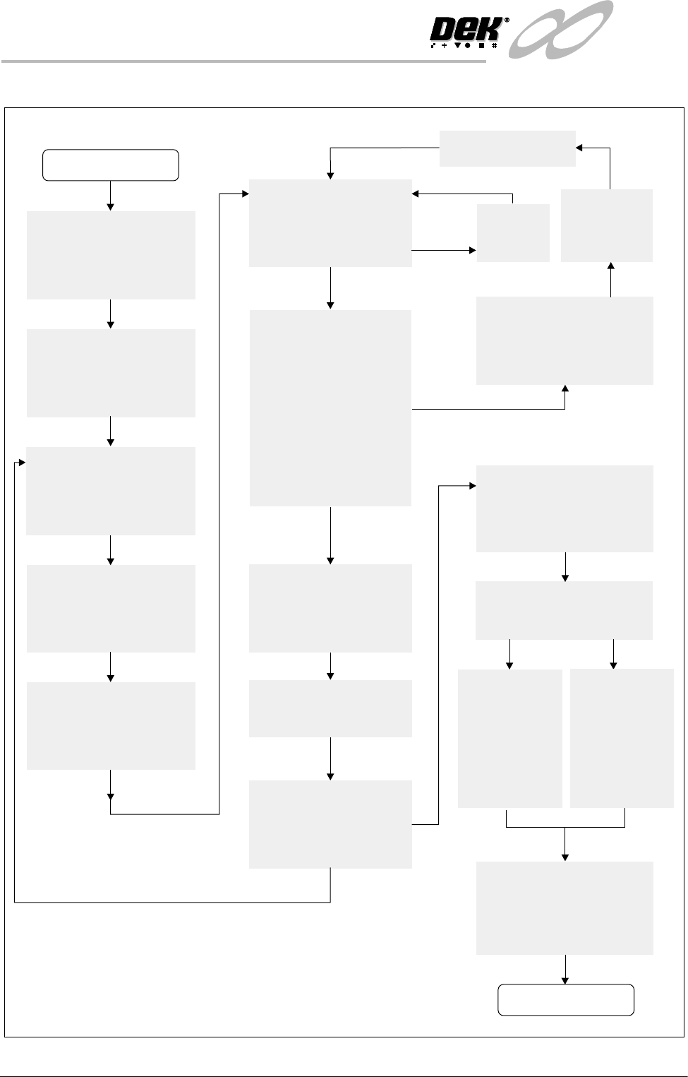
8.10 User Manual Software Version 7
Figure 8-6 2D Inspection Setup Guide
Adjust Lighting:
Adjust so all board pads are
white with sharp edges and
the screen is seen clearly.
Add Limits Sets:
Set wide tolerances so no
alarms occur.
Add Site:
Name, Location Etc
Ensure all pads are within
the search box.
Set Globals as required:
Board and Stencil Inspect
Types etc.
Learn Site / Learn Board:
Adjust board graphic ‘X’
and ‘Y’ accurately
START
Exit out
Auto Scale:
Determine the print closest
to 100% and auto scale on
that pad
Inspect Site:
Paste present data for
all pads are close to
the same value ?
If Board Inspect Type
set to Advanced,
all the paste toggles
white or yellow on the
board ?
More Sites to Teach ?
Add the rest of the sites
using the same light
settings as this first one
NO
NO
NO
NO
YES
YES
YES
YES
Print Board:
Step through the cycle
until a board is printed.
Is it a good print ?
Exit out
Place a clean
board into the
machine.
Clean stencil
Re-adjust Lighting:
Adjust the LED’s to balance
the lighting
Run Product:
Have QC Calc ?
Reset the Globals:
Set the min sites/cycle.
Set 2D Inspect Rate.
Re-adjust the Limit Sets:
The customer may have to
adjust these settings a few
times until the proper
values are found.
SPC Data:
Collect SPC
data on the
2Di. From
this data
derive the
proper ‘limit
sets’ settings.
Trial & Error:
Increase the
‘limit sets’ and
use the data
when it alarms
to derive the
proper
settings.
DONE
New Pre-image taken