DEK INFINITY USER MANUAL.pdf.pdf - 第340页
INFINITY &21680$ %/(5(3/ (1,6+0(1 76 352)/2: 9.56 User Manual Software Versi on 7 5. If the ProFlow unit ’ s base cover is still fi tted continue with Step 6. If the ProFlow unit ’ s base cover has been removed go t…
INFINITY
&21680$%/(5(3/(1,6+0(176
352)/2:
Software Version 7 User Manual 9.55
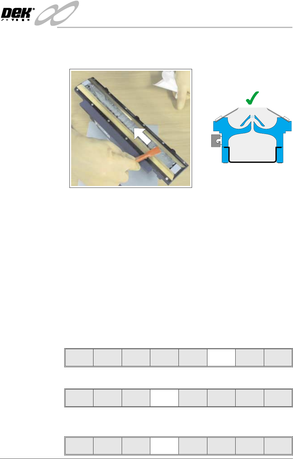
11. Using a spatula, smooth and level the paste to the height of the blades.
NOTE
Pack any excess paste on the spatula between the blades.
12.If necessary clean the wiper blades and skis so that they are not contaminated
with paste.
NOTE
For effective cleaning, DEK recommend the use of IPA impregnated wipes
(Part No.141150).
13.Fit cover to the unit.
14.Fit the transfer head unit to the ProFlow pressure mechanism on the machine.
(Refer to ProFlow Chapter in the Technical Reference Manual for detailed
information on unit removal/fitting.)
The transfer head can be replenished prior to and during a print run.
Prior to a Print Run The transfer head can be replenished prior to selecting Run.
1. If the ProFlow unit is in the home position continue with Step 2. If the
ProFlow unit is in the contact position go to Step 20.
2. Select Setup (F6).
3. Select Setup ProFlow (F4).
4. Select Load Cassette (F4). The message ‘Has the ProFlow unit’s base
cover been removed?’ is displayed.
=
Run Head
Paste
Load
Clean
Screen
Adjust Setup Monitor Maint.
Mode
Load
Data
Edit
Data
Setup
ProFlow
Change
Screen
Change
Tooling
Change
Language
Exit
Change
ProFlow
Load
Cassette
Exit
INFINITY
&21680$%/(5(3/(1,6+0(176
352)/2:
9.56 User Manual Software Version 7
5. If the ProFlow unit’s base cover is still fitted continue with Step 6. If the
ProFlow unit’s base cover has been removed go to Step 12.
6. Select Remove Cover (F8). The message ‘Open the printer cover and
remove the ProFlow unit’s base cover’ is displayed.
7. Open the front printhead cover.
8. Remove the ProFlow unit’s base cover.
9. Close the front printhead cover.
10.Press the System button.
11. Select Exit (F8),
12.Select Yes (F1). The message ‘The ProFlow unit will be placed in the
REAR envelope’ is displayed.
13. If the ProFlow unit is required to be placed in another envelope continue with
Step 14. If the ProFlow unit is required to be placed in the machine preferred
envelope go to Step 18.
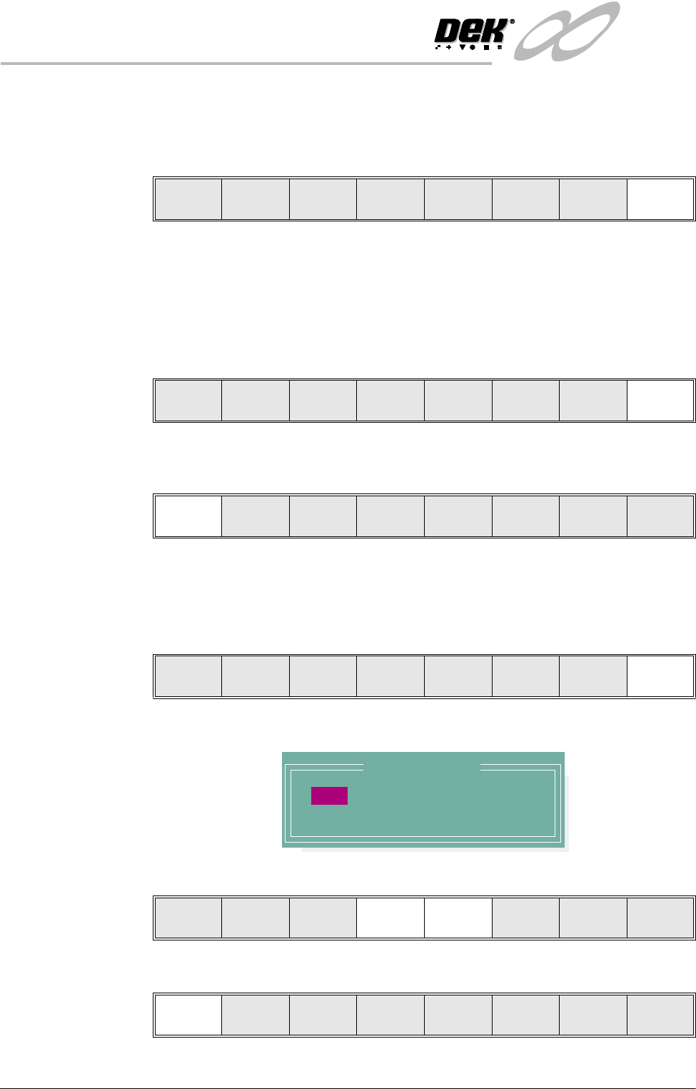
14.Select, Select Another (F8).
The following window is displayed:
15.Use the Next or Previous keys (F4 or F5) to highlight Front.
16.Select Use (F1).
Yes
Remove
Cover
Exit
Yes
Remove
Cover
Proceed
Select
Another
Preferred Envelope
REAR
FRONT
Use Next Previous Exit
Use Next Previous Exit
INFINITY
&21680$%/(5(3/(1,6+0(176
352)/2:
Software Version 7 User Manual 9.57
17.Select Exit (F8).
18.Select Proceed (F1). The ProFlow unit is placed in contact with the screen.
19.Go to Step 23.
20.If the ProFlow unit is in front of the image continue with Step 21. If the
ProFlow unit is at the rear of the image go to Step 23.
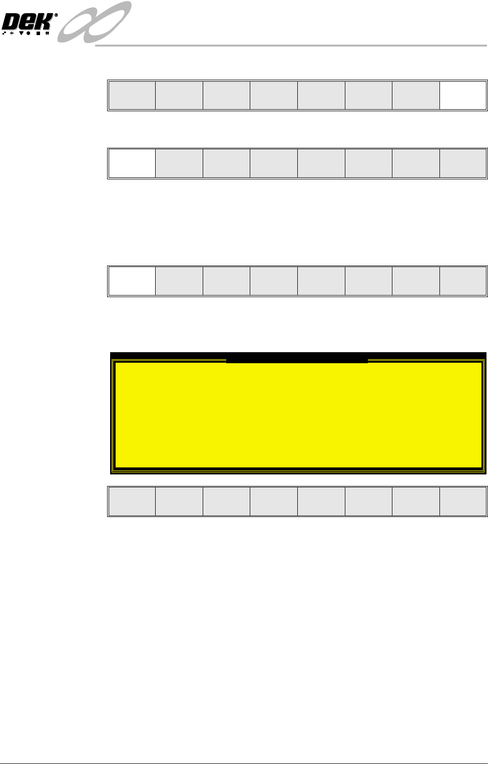
21.Select Run (F1).
If the Camera Idle Position in Set Preferences is set to Behind Rail, the
following window and menu bar is displayed:
Selecting Continue Run clears the warning window and the print cycle
continues.
Selecting End Run clears the warning window, the print cycle is aborted and
control is returned to the ready page.
Use Next Previous Exit
Proceed
Select
Another
Run Head
Paste
Load
Clean
Screen
Adjust Setup Monitor Maint.
Camera Behind Rail Warning
The CAMERA HOME POSITION is set to 'Behind
Rail'
Ensure that no tooling pins or other
obstructions are on the table behind the
rear rail, as these could cause damage to
the camera.
This option will only have an effect for
boards that are less than 250mm wide.
This option can be disabled from the set
preference page.
Continue
Run
End
Run