2OM-1751-003w_G5S.pdf - 第117页
2OM-1751 1-65 1303-001 Comp ID, T ype, and Dir Displayed are the component ID, type and angle of the feeder No. selected in [2]. Note When "Disable" is set for the alternate feeder mode in the pattern program, …

2OM-1751
1-641303-001
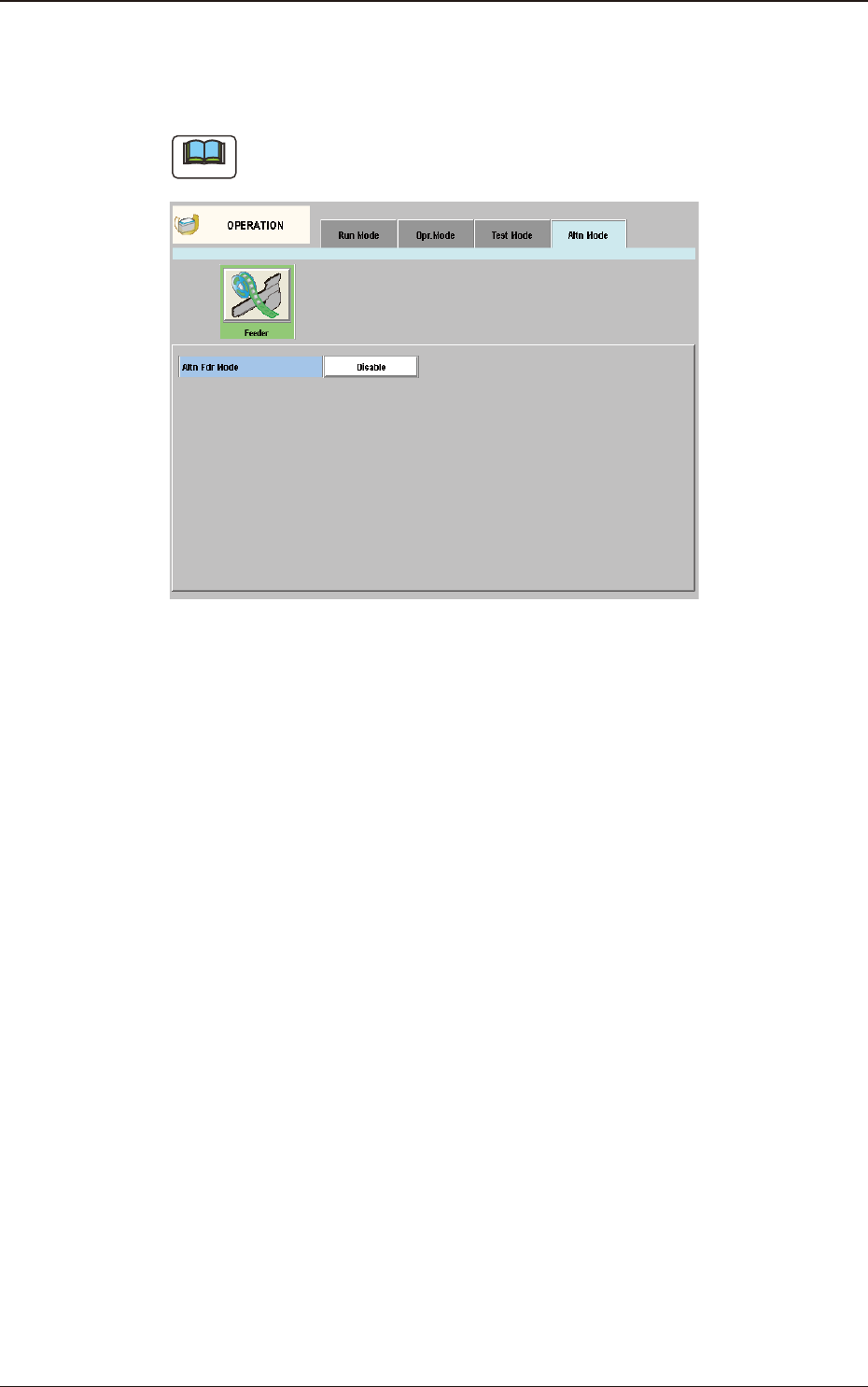
4.4 "Altn Mode" Tab Sheet
[Keep current fdr] Button
When selected, the "Feeder Alternate" function is enabled.
After the components on the specied feeder No., are used up, when there
is any other feeder with the same components, such feeder is used until the
components on the feeder are used up.
Note
(a) The feeders on the opposite block are to be used in this "Feeder
Alternate" operation.
(b) The use of the high-speed head or multi-functional head is available.
(c) The multi-layered tray or vibration stick feeder is not available.
(d) Same Component: Component with the same Component ID
[2] F1 and F2
The feeder Nos. and the destination feeder Nos. are colored, indicating
whether the alternate feeder mode is enabled or disabled.
Light Blue :
Enable
Pink :
Disable
"Disable" is automatically set for the feeder No. where a component shortage
error is detected.
When a feeder is set after component replenishment, "Enable" is
automatically set.
[3] "Set Data" Group Box
The Feeder No. selected in [2] appears in the "Fdr No." text box.
[Enable] and [Disable] Buttons
When the feeder whose parameter "Enable" or "Disable" for the feeder
alternate function must be changed is selected and the [Enable] or the
[Disable] button is pressed, the parameter can be changed manually.
[Enable All F1] Button, [Enable All F2] Button
"Enable" is set for all feeders on the feeder base selected in [2] (Feeder Base
#1 in the window).
[Jump to Alt Fdr] Button
The feeder Nos. selected in [2] are specied as the destination ones for the
alternate feeder mode.
2OM-1751
1-651303-001
Comp ID, Type, and Dir
Displayed are the component ID, type and angle of the feeder No. selected in
[2].
Note
When "Disable" is set for the alternate feeder mode in the pattern program, the
"Altn Mode" window is changed as follows.
"Altn Mode" Window ("Disable" selected) F2A45
4.4 "Altn Mode" Tab Sheet
2OM-1751
1-661303-001
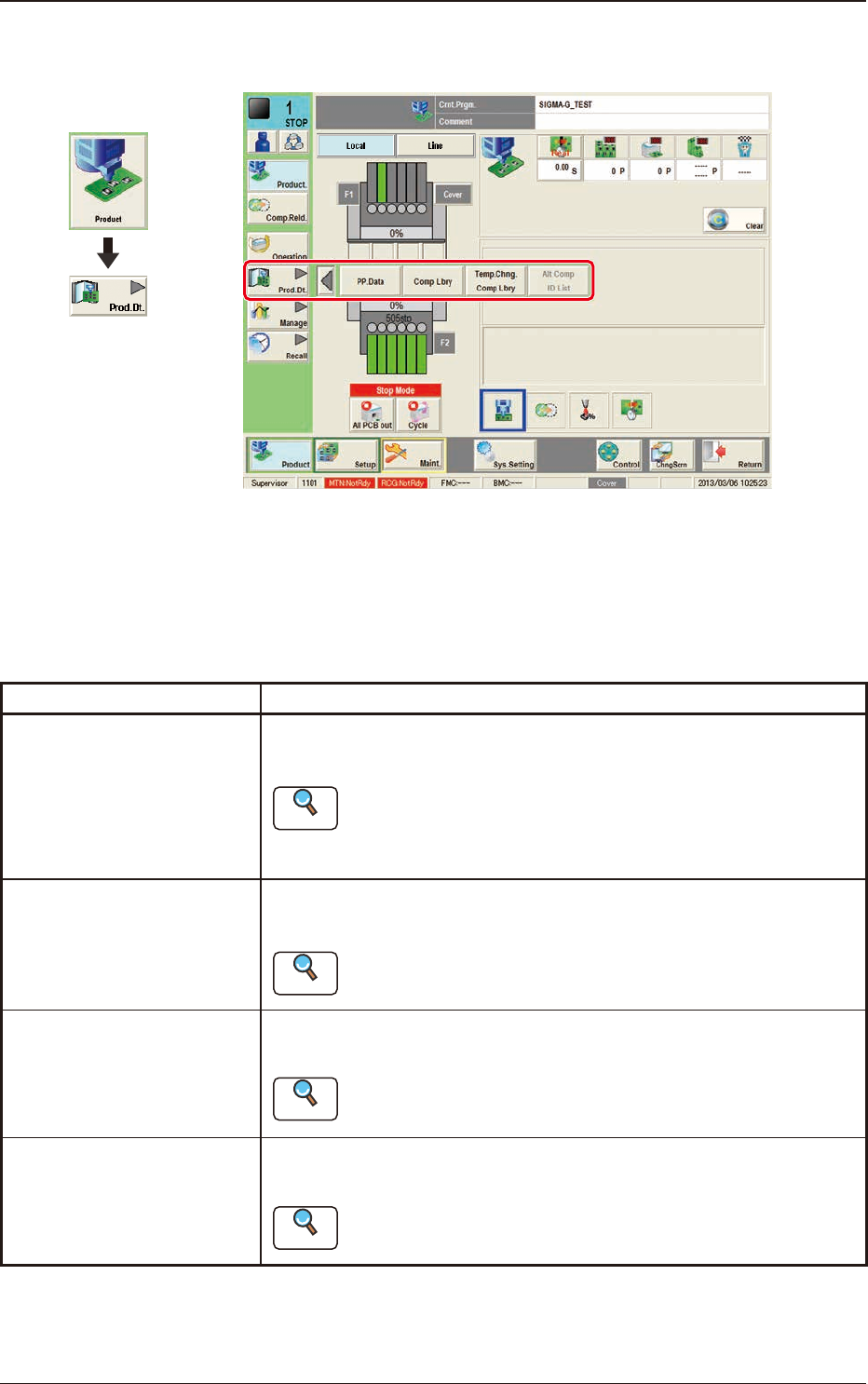
5. "Prod.Dt." Submenu
F2A46
The "Prod.Dt." submenu is provided with the following three menu items. When
each button is pressed, the corresponding window appears.
Please fully understand the purposes of each data for better performance of the
machine.
Buttons Description
PP.Data
Pattern programs must be created for each PCB to be produced.
The automatic operation of this machine is controlled by these pattern programs.
Reference
Refer to "Pattern Program in Chapter 2" for the details.
Comp Lbry
This library stores data related to picks, recognition, and placement of each
individual component.
Reference
Refer to "Component Library in Chapter 3" or "Component
Library in Volume 6" for the details.
Temp.Chng.Comp Lbry
The corresponding tab window enables the operator to change the component library
temporarily during the automatic operation.
Reference
Refer to "2. Component Library in Chapter 3" or "Component
Library in Volume 6" for the details.
Alt Comp ID List
The corresponding window is used to setup the alternative components in placed of
the current components.
Reference
Refer to "3. Alternative Component List" in Chapter 3 for details.
T2A3
5. "Prod.Dt." Submenu
Graphic
Development