2OM-1751-003w_G5S.pdf - 第361页
2OM-1751 6-89 (3) After clicking the upper left of the component image, click the lower right to place the whole component image within a frame. F2F102 (4) Make sure that the whole image is within the frame and press the…

2OM-1751
6-88
Note
In the case of BGA/CSP component where the following electrodes are
arranged with uneven pitches, select [Complex].
F2F99
Notice
When "Simple" is selected as a form of electrodes, it is impossible
to perform a teaching operation on the BGA/CSP components that
are used as electrodes and arranged in unequal pitches.
F2F100
(2) Conrm that the component is in the yellow circle (frame).
When it is in the circle, press the [Yes] button. Otherwise, press the [No]
button.
F2F101
1303-001
7.3 "COMP RCG" Test Window

2OM-1751
6-89
(3) After clicking the upper left of the component image, click the lower right to
place the whole component image within a frame.
F2F102
(4) Make sure that the whole image is within the frame and press the [Fixed]
button.
(5) Press the [Teaching] button to select the teaching method.
Note
When the [Editing] button has been selected, the editing operation is
performed based on the sample data. Press the [Complete] button to return
to the component library teaching window.
F2F103
1303-001
7.3 "COMP RCG" Test Window
2OM-1751
6-90
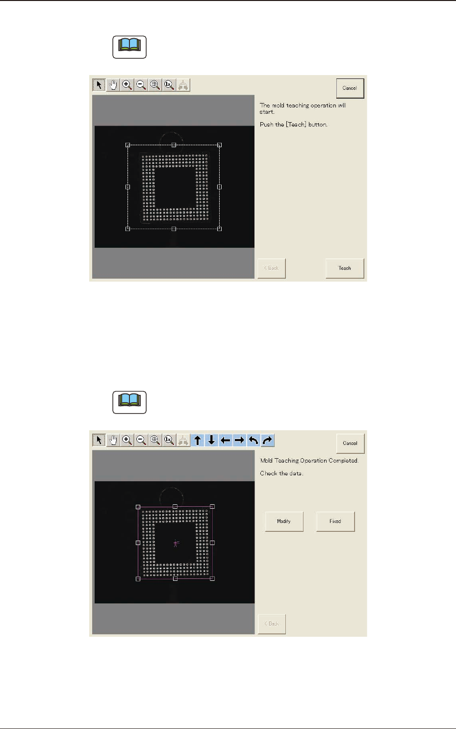
(6) Press the [Teach] button to start the mold teaching operation.
Note
Make sure that the component image is within the frame with dot lines. If
the component is out of the frame, adjust it again.
F2F104
(7) When the mold teaching is completed, check the data and press the [Fixed]
button.
(If the component size or angle is not correct, press the [Modify] button to
correct the graphic image.)
Note
To turn the graphic, click the coordinate graphic and drag either one of the
arrow ends.
F2F105
1303-001
7.3 "COMP RCG" Test Window