2OM-1751-003w_G5S.pdf - 第150页
2OM-1751 2-28 1303-001 (C02_03) Mark Sizes D1 [mm], D2 [mm] and D3 [mm] Set the size of the ducial mark. • Data Input Range Mark Size D1 : 0.50 (for a circle or square, 0.30) to 3.00 Mark Size D2 : 0.00 to 3.00 Note The…
2OM-1751
2-271303-001
(C02_01)
Mark No.
The mark Nos. correspond to the mark codes and the specied parameters of
each ducial mark used in the PEC recognition function. 10 types of mark
codes can be registered for each pattern program.
(C02_02)
Mark Type
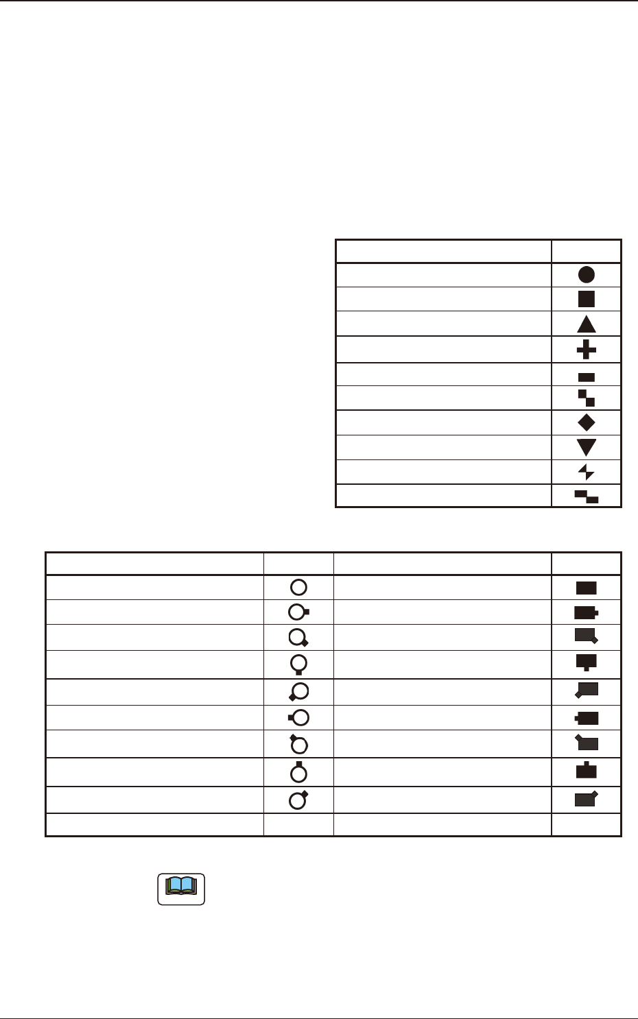
The following options can be selected as shapes of ducial marks.
Mark Type Shape
Round
Square
Equilateral Triangle (Up)
Cross
Rectangle
Checker (Square)
Diamond
Equilateral Triangle (Down)
Bow Tie
Checker (Rectangle)
T2B16
Mark Type Shape Mark Type Shape
Through Hole / No Land
Pad Mark / No Land
Through Hole / No Land (E) Pad Mark / No Land (E)
Through Hole / No Land (SE) Pad Mark / No Land (SE)
Through Hole / No Land (S) Pad Mark / No Land (S)
Through Hole / No Land (SW) Pad Mark / No Land (SW)
Through Hole / No Land (W) Pad Mark / No Land (W)
Through Hole / No Land (NW) Pad Mark / No Land (NW)
Through Hole / No Land (N) Pad Mark / No Land (N)
Through Hole / No Land (NE) Pad Mark / Land (NE)
POP Round land
T2B17
Note
The POP round land cannot be specied as a normal ducial mark.
3.3 Operation
2OM-1751
2-281303-001
(C02_03)
Mark Sizes D1 [mm], D2 [mm] and D3 [mm]
Set the size of the ducial mark.
•
Data Input Range
Mark Size D1
: 0.50 (for a circle or square, 0.30) to 3.00
Mark Size D2
: 0.00 to 3.00
Note
The "Mark Size D3" cannot be used. (Reserved Data)
Reference
Refer to "1.4 Fiducial Mark" in Chapter 4, Volume 1, for details.
(C02_04)
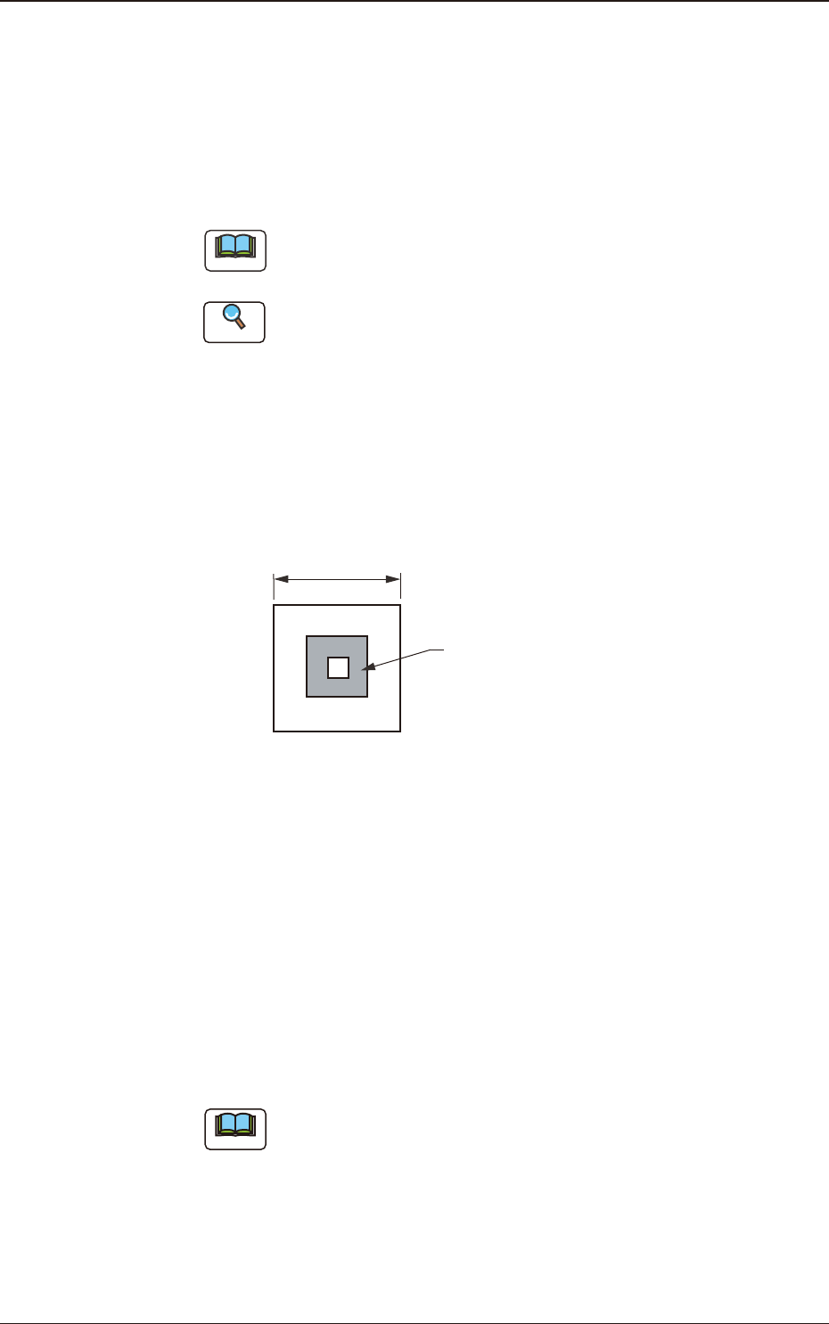
Window Size [mm]
Set the recognition area (complete square) for the PEC recognition function.
Set preferably small values to avoid false recognition and shorten recognition
time.
Fiducial Mark
Window Size
F2B22
•
Data Input Range
1.0 to 10.0
(C02_05)
Mark Image
Select one of the following options as an image of the mark pattern to be
captured by the camera. Select either mode according to the difference in
contrast between a mark pattern and its surroundings to get a clear ducial
images.
Bright (Normal)
: Bright Fiducial/Dark Background
Dark (Inverted)
: Dark Fiducial/Bright Background
Note
Wrong mode selection causes malfunction of the recognition.
3.3 Operation
2OM-1751
2-291303-001
(C02_06)
Mark Level
Set the threshold levels of the ducial marks. In normal cases, set "High".
High
: Both identity and similarity between the shape of a ducial mark
and the real image are detected on a high level.
Middle
: Either identity or similarity between the shape of a ducial mark
and the real image are detected on a middle level.
Low
: Both identity and similarity between the shape of a ducial mark
and the real image are detected on a low level.
Note
(a)
Identity
: Degree of identity between the shapes of the specied
mark and the real image (including the size)
(b)
Similarity
: Degree of similarity between the shapes of the specied
mark and the real image
(C02_07)
Angle [deg]
Set the angle at which a ducial mark should be turned clockwise.
•
Data Input Range
0°, 90°, 180°, 270°
Note
(a) A numerical value must be entered in increments of 90°.
When a value other than the specied increments is entered, the
"Information" window appears, indicating that the entered value
(angle) is changed to "0°", "90°", "180°" or "270°".
(b) When "Thru Hole / Land" is selected in the "Mark Type" (C02_02)
combo box, the color of the angle cell is highlighted and "0 deg" is set
in the "Angle [deg]" text box.
(C02_08)
Lighting Level
Coax, Ring, Option
The brightness level for each lighting is selected from the following items.
Off Std -80% -60% -40% -20%
+20% +40% +60% +80% Auto
3.3 Operation