2OM-1751-003w_G5S.pdf - 第235页
2OM-1751 4-21 1303-001 3.1 "PP Prod. His." Window The PCB production start date and time, and end date and time are recorded. "PP Prod. His." Tab Sheet F2D14 3.1 "PP Prod. His." Window
2OM-1751
4-201303-001
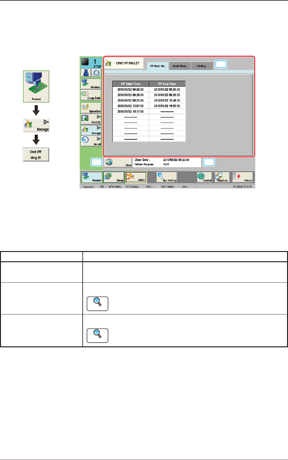
3. "CRNT.PP.MNG.DT" Window
This window enables the operator to conrm the production management data for
the current pattern program.
[2]
[1]
[3]
F2D13
[1] Tabs and Tab Sheets
There are three tab sheets for the "CRNT.PP.MNG.DT" window. When any
tab is pressed, the corresponding tab sheet appears.
Buttons Description
PP Prod. His.
In this tab sheet, the automatic operation starting date and time and
ending date and time are recorded.
Mach.Prfrm.
In this tab sheet, the device management result data is displayed.
Reference
Refer to "2.1 "Mach.Prfrm." Tab Sheet" for each item.
FdrMng.
In this tab sheet, the pick-up data for each feeder is displayed.
Reference
Refer to "2.2 "FdrMng." Tab Sheet" for each item.
T2D3
[2] [Clear] Button
When this button is pressed, all the data parameters are deleted in each tab
sheet for the "CRNT.PP.MNG.DT" window.
[3] Information on Tatalization File Information
The update date and time for the totalization le and pattern program are
displayed in this area.
Graphic
Development
3. "CRNT.PP.MNG.DT" Window
2OM-1751
4-211303-001
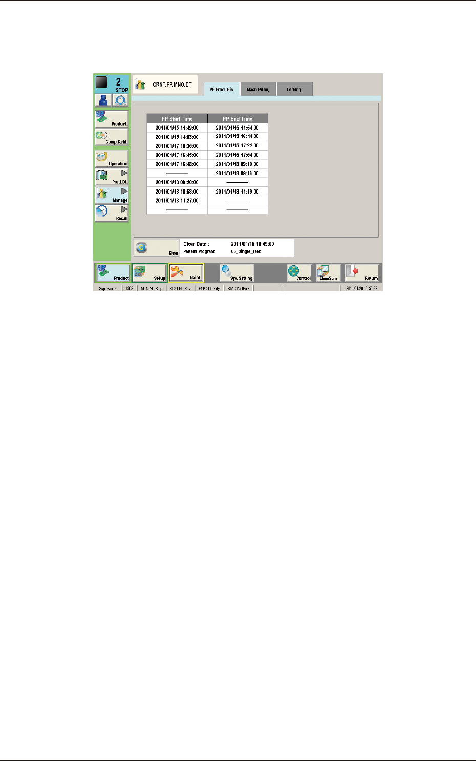
3.1 "PP Prod. His." Window
The PCB production start date and time, and end date and time are recorded.
"PP Prod. His." Tab Sheet F2D14
3.1 "PP Prod. His." Window
2OM-1751
4-22
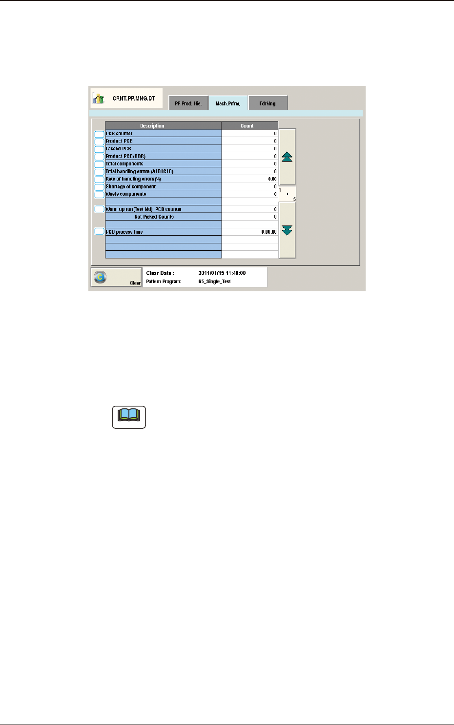
3.2 "Mach.Prfrm," Tab Sheet
When the "Mach.Prfrm," tab is pressed in the "Manage" window, the following
tab sheet appears inside the window.
[1]
[2]
[3]
[4]
[5]
[6]
[7]
[8]
[9]
[10]
[11]
"Mach.Prfrm," Tab Sheet (1/5) F2D15
[1] PCB counter
Shown is the number of produced PCBs.
Counting is implemented when the X/Y beam is zeroed after component
placement operation (when a PCB is nished).
Note
When a particular pattern program is set several times as current one, the
sum total is computed.
[2] Product PCB
The number of produced unit PCBs on multi-unit PCB is summed up.
Counting is implemented when the X/Y beam is zeroed after component
placement operation (when a unit is nished).
When the bad board reject (BBR) function is used, defective unit PCBs are
excluded.
[3] Passed PCB
The number of passed PCBs is counted when the machine is set in the
"PASS" mode.
Counting is implemented when the PCB transfer starts (when the PCB on the
PCB positioning section is transferred to the output conveyor).
[4] Product PCB (BBR)
Shown is the number of defective PCBs summed up when the bad board
reject function (option) is used.
1303-001
3.2 "Mach.Prfrm," Tab Sheet