2OM-1751-003w_G5S.pdf - 第82页
2OM-1751 1-30 1303-001 [1] [2] "Opr.Mode" Tab sheet (3rd page) F2A25 [1] "Opr .Mode" Select The setting is performed in this area for the selected button. When the setting has been changed, press the …

2OM-1751
1-291303-001
4.2 "Opr.Mode" Tab Sheet
When the [Opr.Mode] tab is pressed, the "Opr.Mode" tab sheet (1st page) appears
as an initial one.
[1]
[2]
"
Opr.Mode
"
Tab sheet (1st page) F2A23
[1]
"
Opr.Mode
"
Tab sheet (2nd page) F2A24
4.2 "Opr.Mode" Tab Sheet
Graphic
Development
2OM-1751
1-301303-001
[1]
[2]
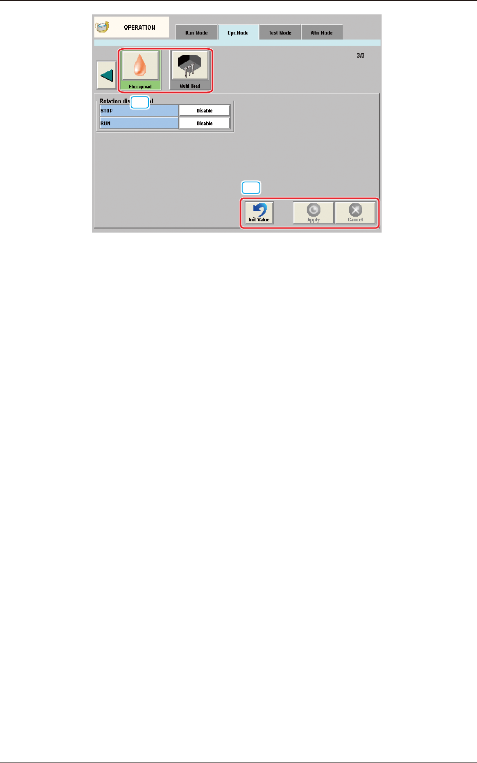
"Opr.Mode" Tab sheet (3rd page) F2A25
[1] "Opr.Mode" Select
The setting is performed in this area for the selected button.
When the setting has been changed, press the [Apply] button to apply the
setting.
[2] Common Button
[Init Value] Button
When pressed, the set condition parameters are returned to the initial values.
[Apply] Button
When pressed, the changed setting is applied.
[Cancel] Button
When pressed the changed setting is returned to the one prior to the change.
4.2 "Opr.Mode" Tab Sheet
2OM-1751
1-311303-001
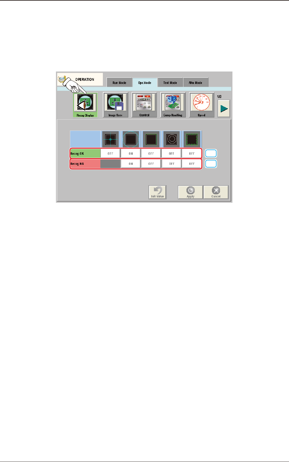
4.2.1 Recog Display
When the [Recog Display] button is pressed on the "Opr.Mode" tab sheet, the
following window appears.
In this window, the graphic display setting when the recognition results are
displayed, is performed.
[1]
[2]
F2A26
[1] Recog OK
When the result of recognition is normal, the graphics of the items for which
the setting has been "ON" using the following buttons, are displayed.
[Cross] Button
When selected, this displays a crosshair at the center of the recognized
object.
[Circle] Button
When selected, this displays a circle at the center of the recognized object.
[Outside] Button
When selected, this displays the outline of the recognized object.
[Nozzle Outside] Button
When selected, this displays the outline of the vacuum nozzle that was used
to recognize a component.
[Detect Pos] Button
When selected, this displays the detection area, detected corner or edge
position.
4.2 "Opr.Mode" Tab Sheet