2OM-1751-003w_G5S.pdf - 第161页
2OM-1751 2-39 1303-001 PCB Bottom [mm] When PCBs with some components already mounted on the lower surfaces (back) by the input machine are transferred to this machine, be sure to enter the thickness of the highest compo…
2OM-1751
2-381303-001
(D01_03)
Pre-PL cmpnt thkns
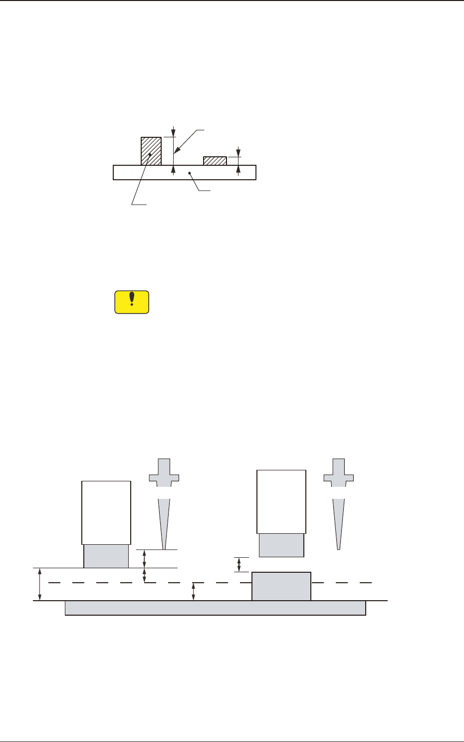
PCB Top [mm]
When some components are placed previously on a PCB by the input
machine, etc., and transferred to the main machine, be sure to enter the
thickness of the tallest component of all in the text box.
Tallest Previously Placed Component
Set this thickness in the text box.
PCB
F2B34
•
Data Input Range
0 to 25.400
Notice
(a) When components are placed previously and the main machine
is operated with "0.00" in this text box, some of the previously
placed components may interfere with components to be
placed newly.
(b) It is advisable that placement data should be created such that
shorter components are placed before the tallest one.
(c) When the specied thickness of a previously placed component
differs from the actual one, the light emitter of the Side View
Camera may interfere with the previously placed component.
2.0 mm
4.0 mm
2.0 mm
3.0 mm
2.0 mm
NL Origin Position NL Origin Position
Light
Emitter
Light
Emitter
Previously
Placed
Component
PCB
Placement Level
No Previously Placed Component Previously Placed Component
F2B35
3.4 Control
2OM-1751
2-391303-001
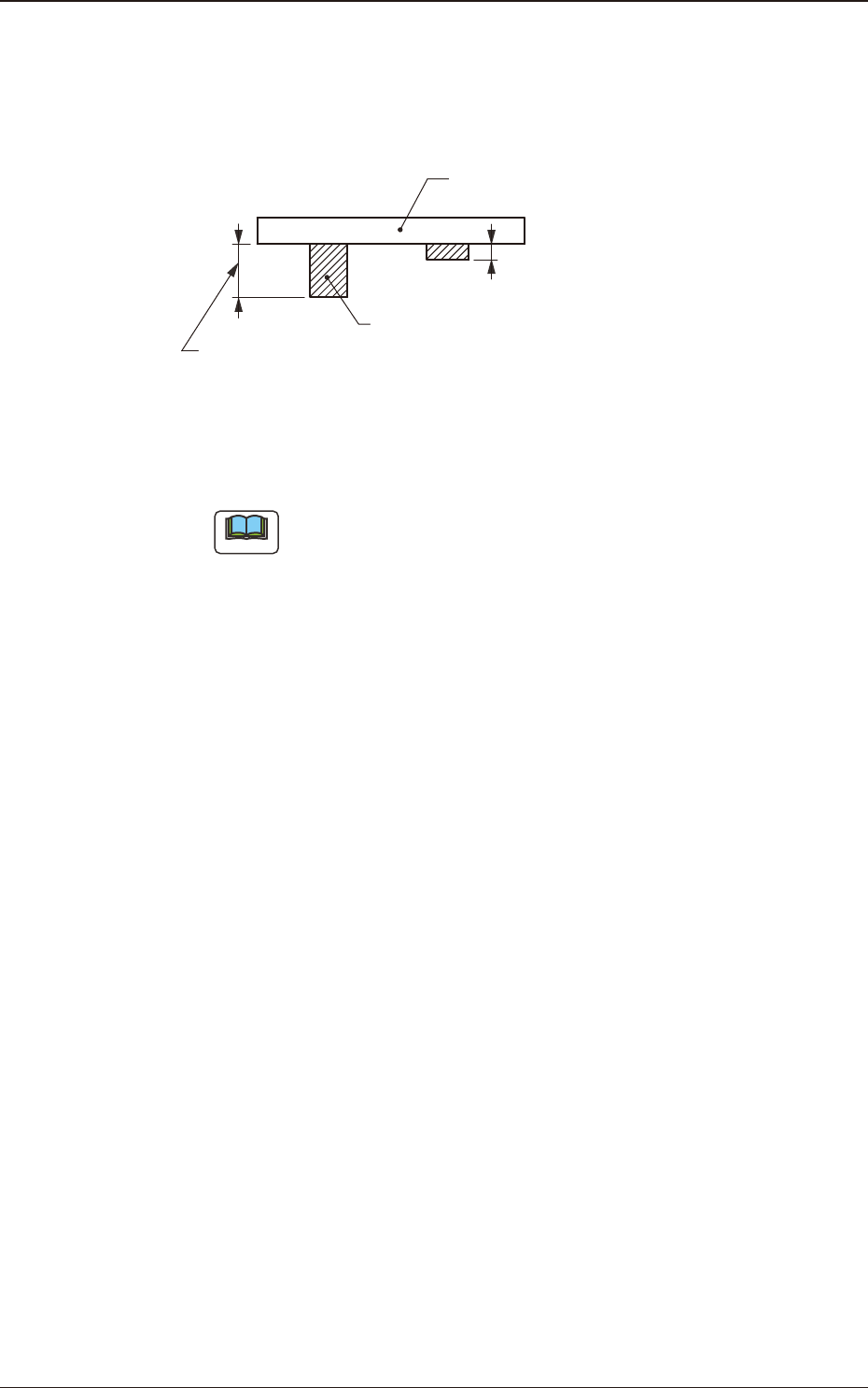
PCB Bottom [mm]
When PCBs with some components already mounted on the lower surfaces
(back) by the input machine are transferred to this machine, be sure to enter
the thickness of the highest component in the text box.
Tallest Previously Placed Component
PCB
Set this thickness in the text box.
F2B36
•
Data Input Range
0 to 30.000
Note
(a) The set parameter is used to determine the position (elevation) of the
rst backup table when the PCB is transferred to the PCB positioning
section.
(b) When components are placed previously and the main machine is
operated with "0.00" (no previously placed components) in this text
box, the support pins may interfere with some of the previously
placed components on the back of PCB while the PCB is being
transferred to the PCB positioning section.
(D01_04)
PEC expansion correction
"Enable" or "Disable" for the PEC Recognition Extension Correction, is
selected in this selection box.
3.4 Control
2OM-1751
2-401303-001
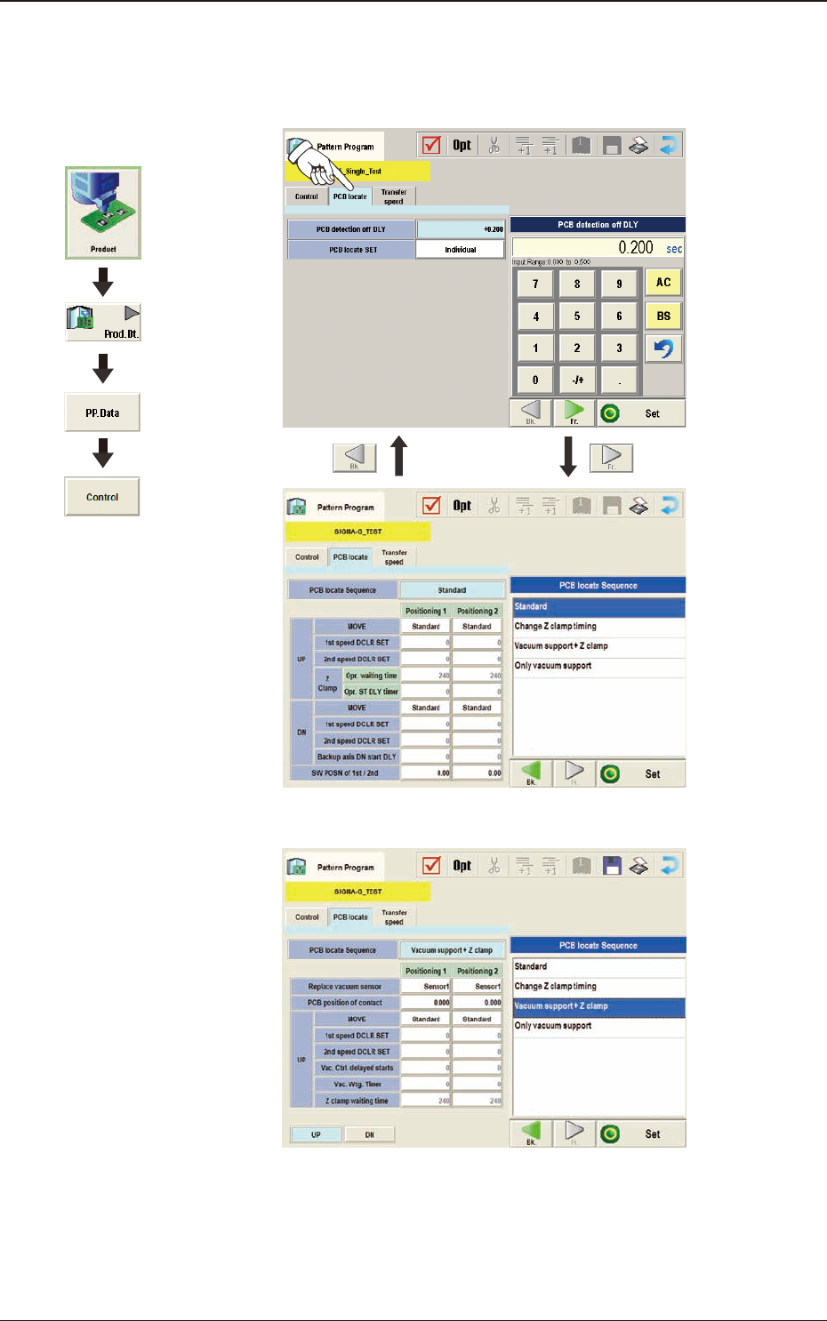
(D02) PCB locate Data
When the [PCB locate] tab is pressed in the "Control" window, the following
tab sheet appears.
F2B37
In PCB Vacuum Support F2B38
Graphic
Development
3.4 Control