2OM-1751-003w_G5S.pdf - 第146页
2OM-1751 2-24 1303-001 (C01_03) Image When "Enable" is selected, set one of the following options as an image recognition mode. Disable : The image recognition function is not used. Enable : The image recogniti…
2OM-1751
2-231303-001
•
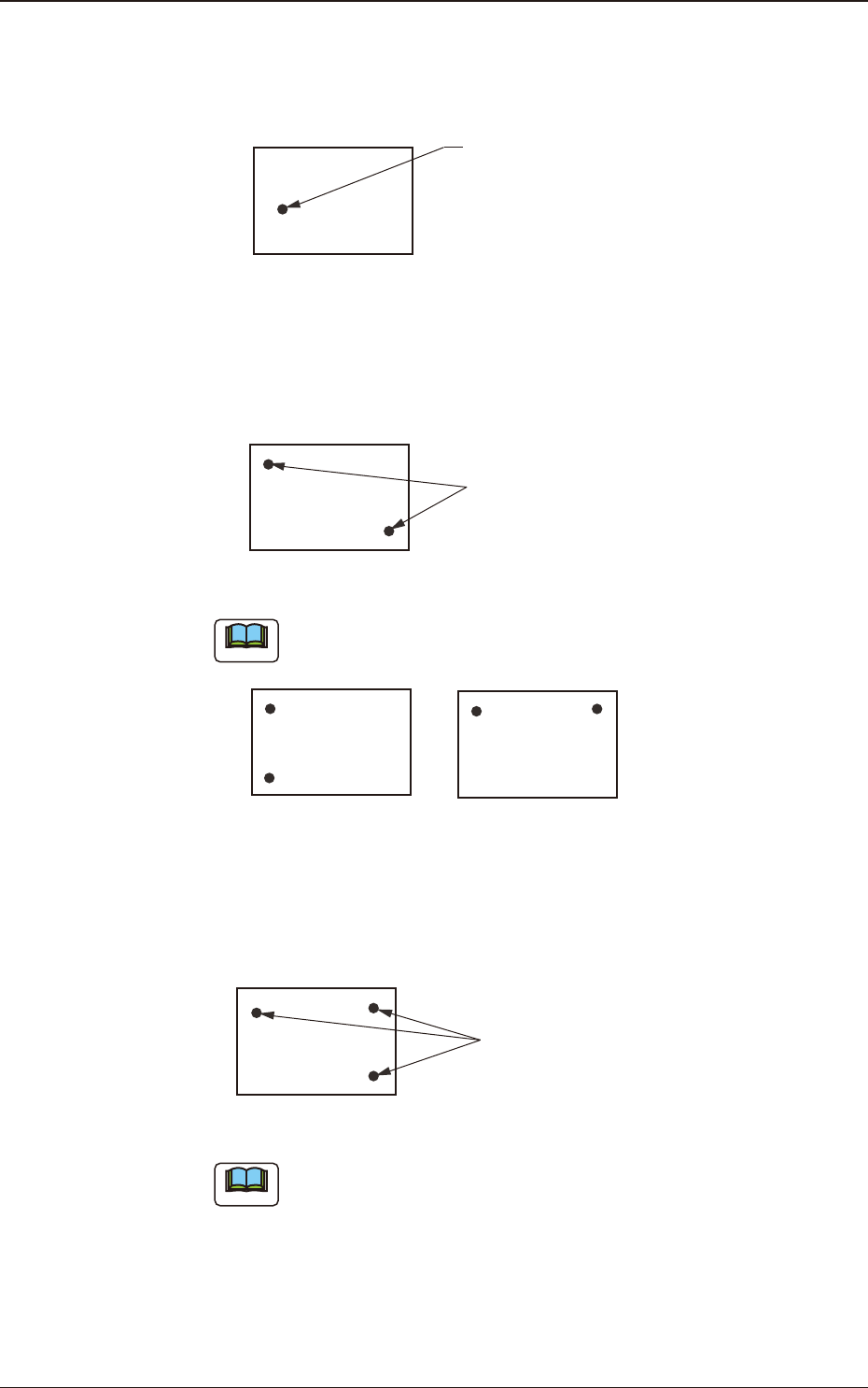
1-Point Recognition
Only the X and Y elements are corrected. The θ element (expansion, etc.) is
not corrected.
Fiducial Mark
F2B16
•
2-Point Recognition
Specify ducial mark positions so that one ducial mark is kept as diagonally
away from the other as possible.
Fiducial Mark
PCB
F2B17
Note
Avoid making positional relation such as ducial marks aligned vertically
or horizontally with each other as shown below.
F2B18
•
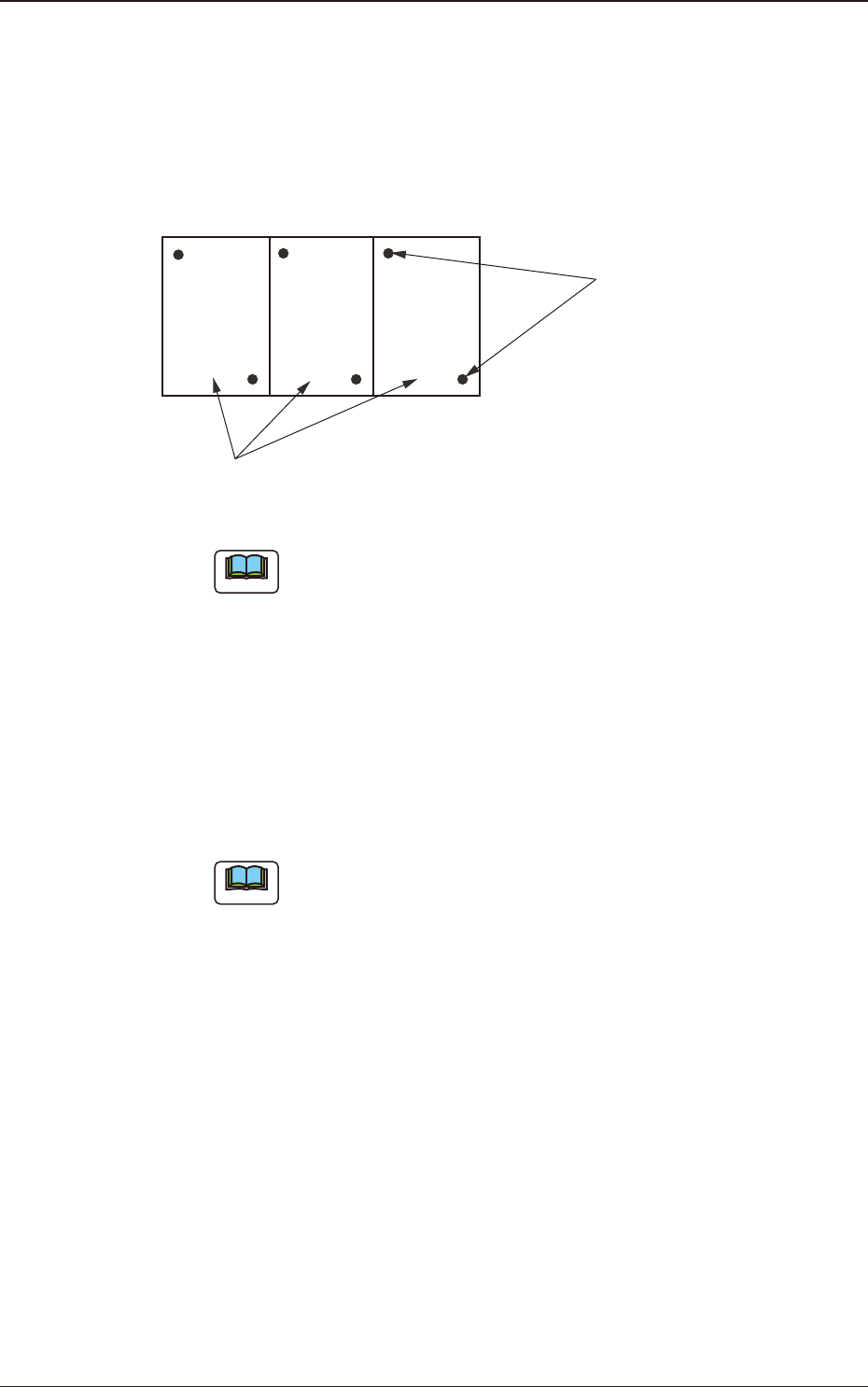
3-Point Recognition
Specify ducial mark positions so that the triangle are formed by connecting
the three points (three ducial marks) becomes as large as possible.
Fiducial Mark
F2B19
Note
When any two of the three ducial marks are designated to be positioned
as close as possible to each other, the results of the correction will be
almost the same as "2-Point Recognition".
3.3 Operation
2OM-1751
2-241303-001
(C01_03)
Image
When "Enable" is selected, set one of the following options as an image
recognition mode.
Disable
: The image recognition function is not used.
Enable
: The image recognition function is used.
Unit PCB (Multi-Unit PCB)
Fiducial Marks
F2B20
Note
When the global recognition function is used together with the image
recognition function, both recognizing actions take place but the placement
coordinates are corrected according to the result of the image recognition.
(C01_04)
Local
Select one of the following options to determine whether or not the ducial
mark on each component placement point should be recognized.
Disable
: The local recognition function is not used.
Enable
: The local recognition function is used.
Note
(a) When "Enable" is set in the text box, the deviation of each component
placement point can be corrected.
(b) A component placement point and each recognition mode can be
specied in "(D02_09) V" of the placement data (P-data) and the
coordinates and mark code of a ducial mark can be designated in
(D02_12), (D02_13), and (D02_14) of the placement data (P-data).
3.3 Operation

2OM-1751
2-251303-001
(C01_05)
Zones 1, 2, 3, 4, and 5
When the PEC recognition mode is set with "All" function enabled, the
coordinates and mark code of each ducial mark must be set.
1st Point X [mm] (Horizontal) and Y [mm] (Vertical)
Set the coordinates of the rst ducial mark in the text boxes.
1st Point Mark Code
Set the mark code of the rst ducial mark in this text box.
2nd Point X [mm] (Horizontal) and Y [mm] (Vertical)
Set the coordinates of the second ducial mark in the text boxes.
2nd Point Mark Code
Set the mark code of the second ducial mark in the text box.
3rd Point X [mm] (Horizontal) and Y [mm] (Vertical)
Set the coordinates of the third ducial mark in the text boxes.
3rd Point Mark Code
Set the mark code of the third ducial mark in the text box.
Reference
Refer to "(C02) PEC Recognition Mark Data" for the mark codes.
3.3 Operation