CP45FVNEO Maintenance Reference (Eng, Ver3).pdf - 第130页
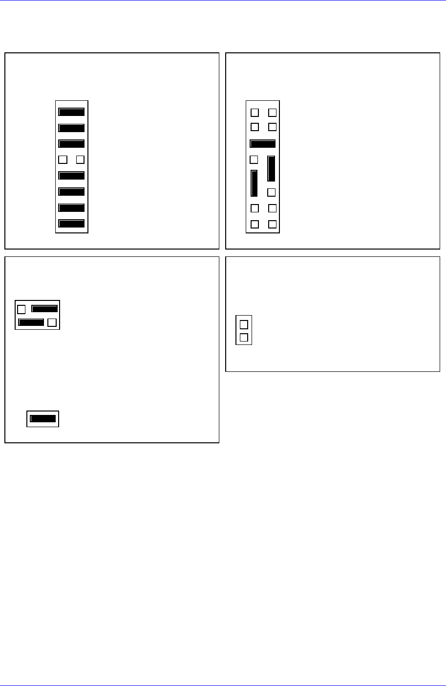
Samsung Component Placer CP45NEO Series Maintenance Guide 7.5. Board Jumper Setting J1 2 : 8 E PRO Ms = 4M B 2 1 15 16 J1 2 C o nf i g ur a t io n 3 : 512 K × 8E P R O M s J 11 : EPRO M boot ing GPI O 0 GPI O 1 GPI O 2 G…

Inspection of the Controller
7-21
7.4. Inspection of the Motor Part
Check following items.
7.4.1. X-axis
Check if the power of the motor drive is normal. Initially, ‘r 0’ is indicated on the
LED display window. (This means the current RPM of the motor is 0.)
Check to see if the command connector from the axis board is connected properly.
Check the status of encoder line and power supply line.
Check the connector terminal status and connection status of each drive.
Move the head manually and check the change of motor RPM in the LED Display
with the machine remaining in READY-OFF state.
At this time, change the direction of movement manually and check if the sign of the
RPM shown in the LED Display is changed
7.4.2. Y-axis
Check if the power of the motor drive is normal. Initially, ‘r 0’ is indicated on the
LED display window. (This means the current RPM of the motor is 0.)
Check to see if the command connector from the axis board is connected properly.
Check the status of encoder line and power supply line.
Check the connector terminal status and connection status of each drive.
Move the X-Frame manually and check the change of motor RPM in the LED
Display with the machine remaining in READY-OFF state.
At this time, change the direction of movement manually and check if the sign of the
RPM shown in the LED Display is changed.
7.4.3. Z1~Z6, S, W axis
Check if the power of the motor drive is normal. Initially, ‘r 0’ is indicated on the
LED display window. (This means the current RPM of the motor is 0.)
Check to see if the command connector from the axis board is connected properly.
Check the status of encoder line and power supply line.
Check the connector terminal status and connection status of each drive
Move the head manually and check the change of motor RPM in the LED Display
with the machine remaining in READY-OFF state.
At this time, change the direction of movement manually and check if the sign of the
RPM shown in the LED Display is changed.
7.4.4. R1/2, R3/4, R5/6 axis (THETA1, THETA2, THETA3)
Check the power of the motor drive.
Check to see if the command connector from the axis board is connected properly.
The command connector is connected to the CN2, CN5, CN8 of the STEP I/F board.
Check to see if the R1/2(THETA1), R3/4(THETA2), R5/6(THETA3) from the CN3,
CN6, CN9 of the STEP I/F board is connected properly.
Samsung Component Placer CP45NEO Series Maintenance Guide
7.5. Board Jumper Setting
J12 : 8 EPROMs = 4MB
21
15 16
J1 2
Configuration 3 : 512K
×
8EPROMs
J11 : EPROM booting
GPIO 0
GPIO 1
GPIO 2
GPIO 3
GPIO 4
GPIO 5
GPIO 6
GPIO 7
21
7
15 16
8
J11 Us er Code Installed
User - Def iinab le
User - Def iinab le
User - Def iinab le
In=Flash; Ou t=EPROM
User - Def iinab le
User - Def iinab le
User - Def iinab le
User - Def iinab le
EPROMs Selected (Factory configuration)
J13 : Primary Source VMEbus +5V STBY
2
1
J13
6
5
Primary Source VMEbus +5V STBY
Secondary Source Onboard Battery
J1 : System Controller
21
J1
System Controller (Factory configuration)
J14 : SCSI terminator disabled
2
1
J1 4
On -Bo a rd SCSI Bu s Terminat o r Disab led
Figure 7-5. MVME162-220 Jumper Setting
7-22
Inspection of the Controller
7-23
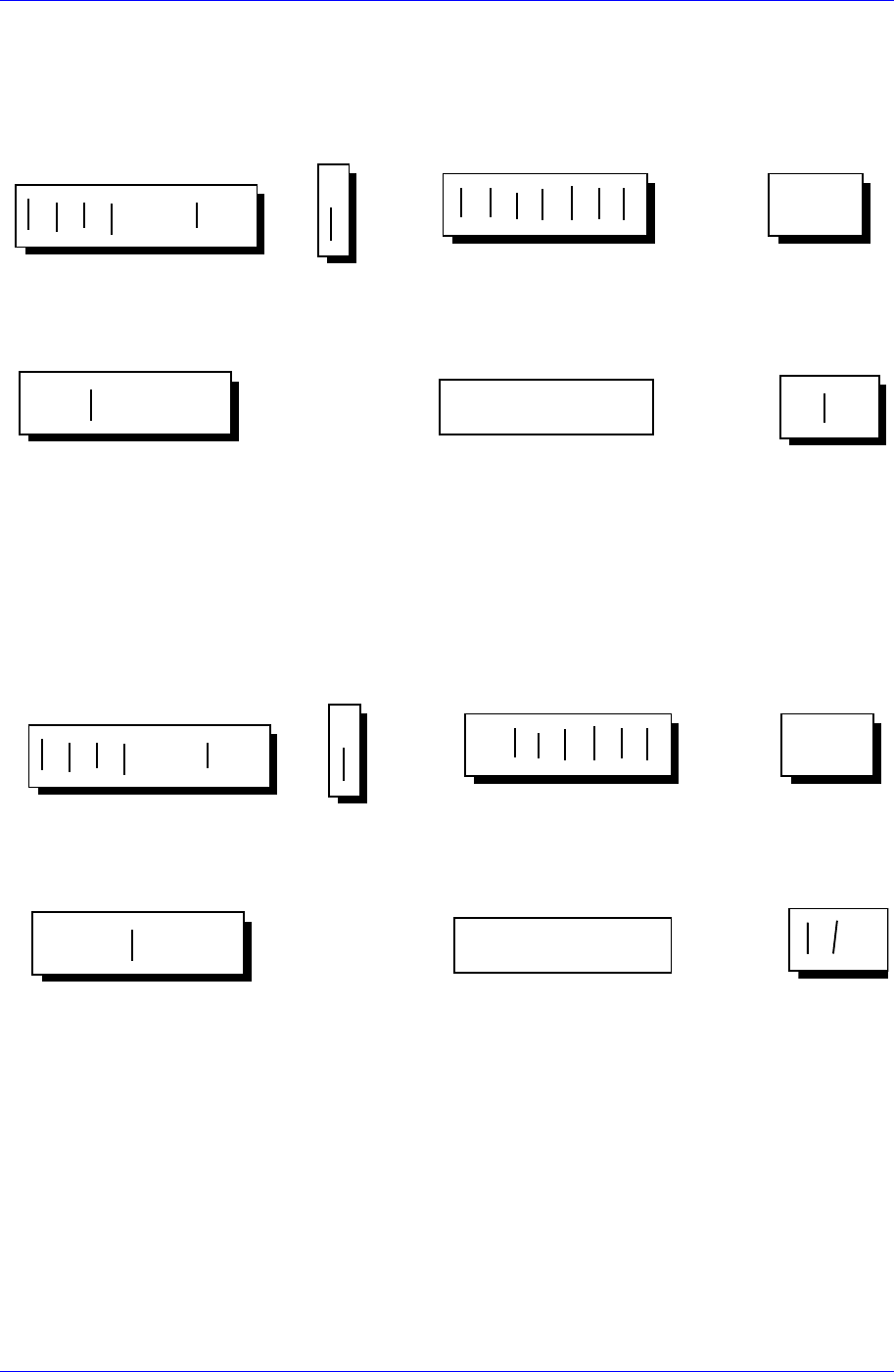
●●●●●●●
●●●●●●●
●●●●●●●●
●●●●●●●●
13579111315
2 4 6 8 10 12 14 16
●
●
●
●●●●●●●
●●●●●●●
JP 5
JP 6
1
2
3
JP 7
135791113
2468101214
●●●
●●●
●●●
●●●
JP 8
JP 9
135
246
135
246
●●●●●●●
●●●●●●●
■■
■■■■■ ■
135791113
2 4 6 8 10 12 14
12345678
JP 10
SW 1
●●●●●●●●
●●●●●●●●
1 3 5 7 9 11 13 15
246810121416
●
●
●
JP 5
JP 6
1
2
3
JP 7
135791113
2468101214
●●●●●●●
●●●●●●●
■■■
■■ ■■ ■
135791113
2468101214
12345678
JP 10
SW 1
H1/2 axis board
●●●●●●●●
●●●●●●●●
●
●
●
●●●●●●●
●●●●●●●
●●●
●●●
JP 8
JP 9
135
246
135
246
●●●
●●●
XY axis board
●●●
●●●
Figure 7-6. XY, H1/2 Axis Board Jumper Setting