YRM20_Mainte_E.pdf - 第109页
4. 6-month maintenance 3-42 Chapter 3 Periodic maintenance items 6 Detach t he filter of co ntrol box. The filters are located at front and lateral side. Detach the machine front filter with filter cover by loosening 2 mo…
4. 6-month maintenance
3-41
Chapter 3 Periodic maintenance items
4.2 Base section
4.2.1 Cleaning the fan filter of control box
The control box section, which controls the machine, is equipped the air intake fan and filter. This filter
should be cleaned once 6-month, though it depends on the machine operating condition.
1
e
Prepare for work.
1. Press the emergency stop button and detach
the feeder exchange carriage of machine
front side.
2. Close applications and turn OFF the machine
power.
2
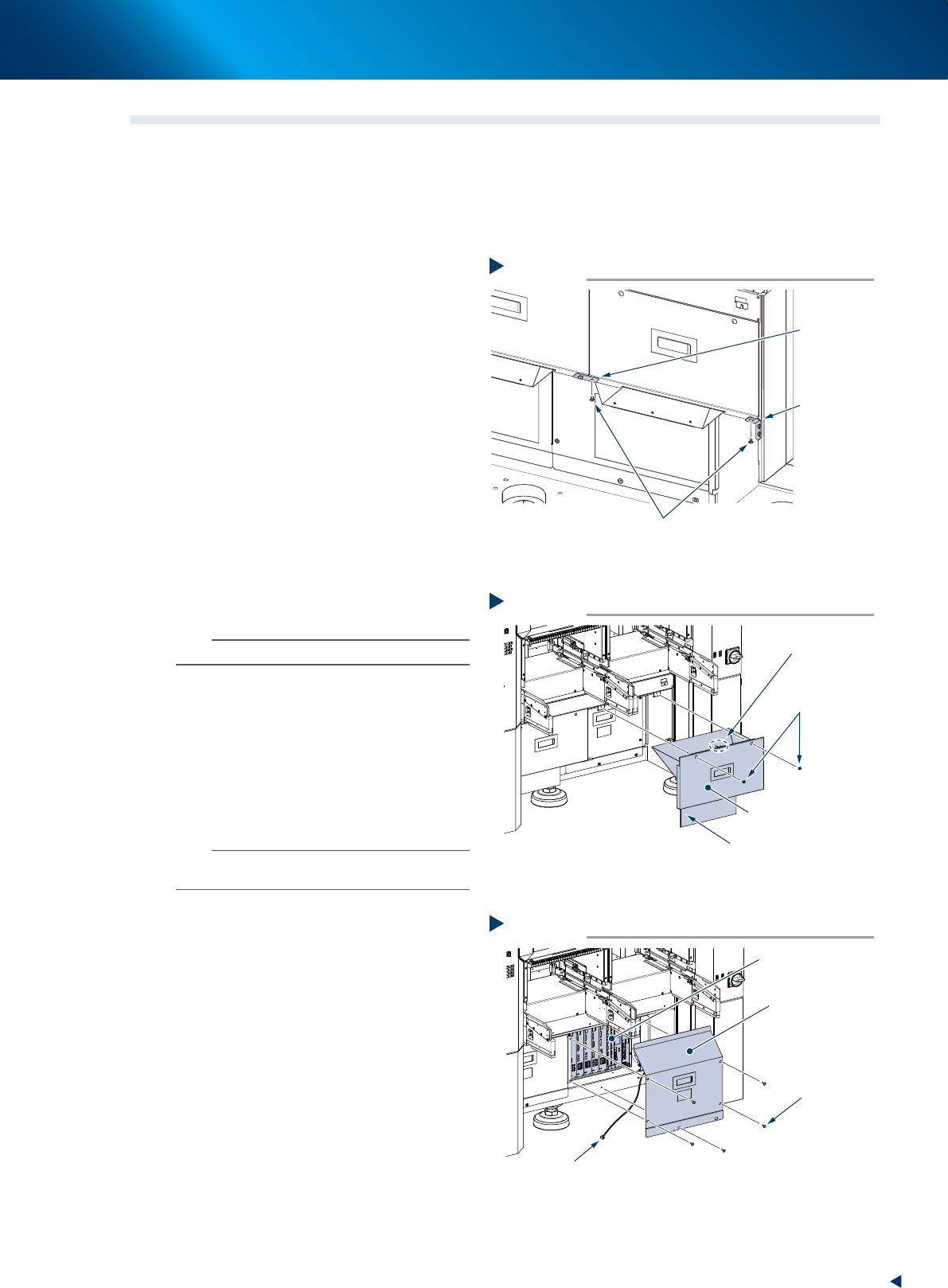
Remove the mounting screws installed
at left-right connecting point and
connecting point to machine body of
the safety cover (hereinafter referred to
as cutter cover) of tape cutter using
Phillips screwdriver.
3
Detach the cutter cover.
1. Remove the mounting screw (at front right of
machine front) using Phillips screwdriver.
2. Detach the cutter cover by pulling it out to
front.
n
NOTE
The cutter cover is installed an interlock key.
4
Detach the inner cover.
1. Remove 5 mounting screws of the inner
cover (front right) using Phillips screwdriver.
2. Detach the inner cover.
3. The ground wire is connected at the center
of the inner cover reverse side. Remove the
wire mounting screw using Phillips
screwdriver.
n
NOTE
The mounting screw of ground wire is used with a tooth
lock washer. Be careful not to lose it upon detaching.
5
Clean around the control box before
detaching the filter upon finding the
dust and dirt around the control box.
Removing the mounting screw
Step 2
Mounting screw
Left-right
connecting
point
Connecting
point to
machine body
53386-KMX-00
Step 3
Detach the cutter cover
Cutter cover (front right)
Mounting screw
Interlock key
Preventing cut debris splattering sheet
53380-KMX-00
Step 4
Detaching the inner cover
Inner cover
(front right)
Mounting screw
Control box
Ground wire mounting screw
53381-KMX-10
4. 6-month maintenance
3-42
Chapter 3 Periodic maintenance items
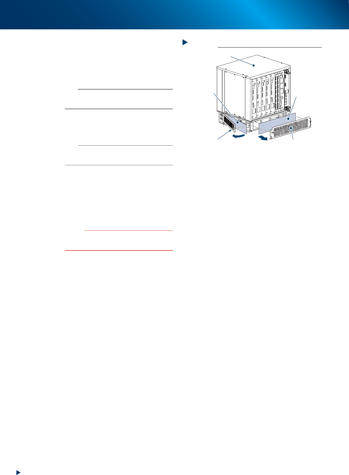
6
Detach the filter of control box.
The filters are located at front and lateral side.
Detach the machine front filter with filter cover
by loosening 2 mounting screw by hand.
Detach the machine lateral side filter by
loosening a mounting screw by hand.
n
NOTE
The multiple cables are connected to the control box.
Disconnect some cables as necessary when the access to
filter is interfered.
7
Clean the filter with a vacuum cleaner
or a vacuum assembly removing the
dust adhering to the filter.
n
NOTE
When the dust or dirt cannot be removed, or the filter
itself is deteriorated, it requires the filter replacement
detaching the cover.
8
Return the filter to its original position
by the reverse procedure of detaching
it.
9
Return the covers.
1. Attach the inner cover.
2. Attach the tape cutter cover.
c
CAUTION
• Be careful not to forget the reconnecting of ground wire
to the inner cover.
• Be careful not to tuck the cable upon attaching covers.
Detaching the filter of control box
Step 6
Control box
Front filter
Lateral side filter
Filter cover
Filter mounting screw
53382-KMX-00
5. 1-year maintenance
3-43
Chapter 3 Periodic maintenance items
5. 1-year maintenance
This section describes 1-year maintenance items.
5.1 HM head: Cleaning the spline shaft interior
Generally, the spline shaft interior should be cleaned once a year. Perform the following procedures.
1
Store all the nozzles to nozzle station.
1. Open the [Unit] - [Head] screen.
2. Select any head unit from "Table Select".
3. Press the [Nozzle Change] button.
4. Select "ALL" for "Head Number" and select
"Store Nozzle" for "Nozzle Type" on the
"Nozzle Change" screen.
5. Press the [OK] button to return all nozzles to
the nozzle station.
n
NOTE
When the nozzle station is not equipped, press the
emergency stop button and detach the nozzles by hand.
e
2
Move the head unit.
1. Press the emergency stop button and detach
the feeder exchange carriage.
2. Open the machine safety cover and move
the head unit to convenient position to work.
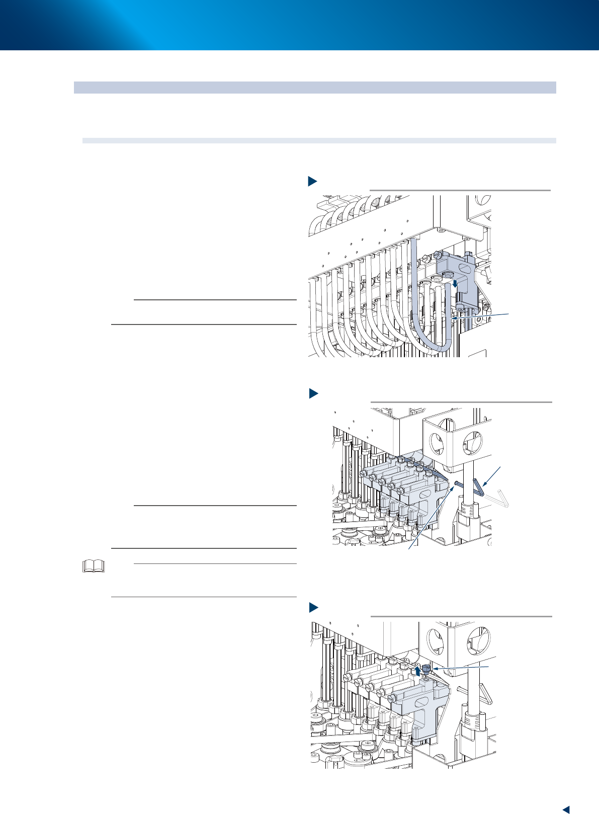
3
Pull out the lower end of air hose.
4
Fix the Z-axis as shown in the figure
right, by placing the Z-axis linear scale
hidden by shaft, and by inserting a
hexagon wrench into the Z-axis fixing
hole.
n
NOTE
As there are cables around the head and they may
prevent a hexagon wrench to insert into the hole. In such
case, use a wire (less than
φ
2.5mm) or similar instead to
mount the Z-axis.
TIP
The common type hexagon wrench can fix approximately
5 heads at once. HM head unit has 10 heads, so cleaning
them in 2 part is recommended.
5
Detach the maintenance bolt using a
flat-head screwdriver or a precision
spanner.
6
Prepare for cleaning.
1. Place a paper cup or a lint-free cloth
beneath the target head.
2. Refill the ethanol into cleaning kit.
53354-KMX-10
Step 3
Removing the air hose and maintenance bolt
Air hose
Step 4
Fixing the Z-axis
Hexagon wrench
φ2.5mm
Z-axis fixing hole
53355-KMX-10
Detaching the Maintenance bolt
Step 5
Maintenance bolt
533H7-KMX-00