YRM20_Mainte_E.pdf - 第136页
8. Others 3-69 Chapter 3 Periodic maintenance items 5 Pr eclean inside of sha ft with brush to remo ve dir t or forei gn objects easil y . 1. Inser t spline brush (KMB -M3858-00X) de eply into the noz zle shaft. T urn it…
8. Others
3-68
Chapter 3 Periodic maintenance items
8. Others
8.1 Cleaning inside of nozzle shaft on RM head unit
When the vacuum level does not go down to 140 or less while nozzle is detached from RM head unit,
replace with new filter as a general. If vacuum level does not go down to the standard value even after
replacing filter, The air path in spline shaft may be dirty.
In this case, it is required to clean the inside of nozzle shaft.
Note that clean 18 shafts of all heads as a rule even the vacuum level of one head does not go down to the
standard value as shaft inside of other heads may be dirty.
1
Store all nozzles to nozzle station.
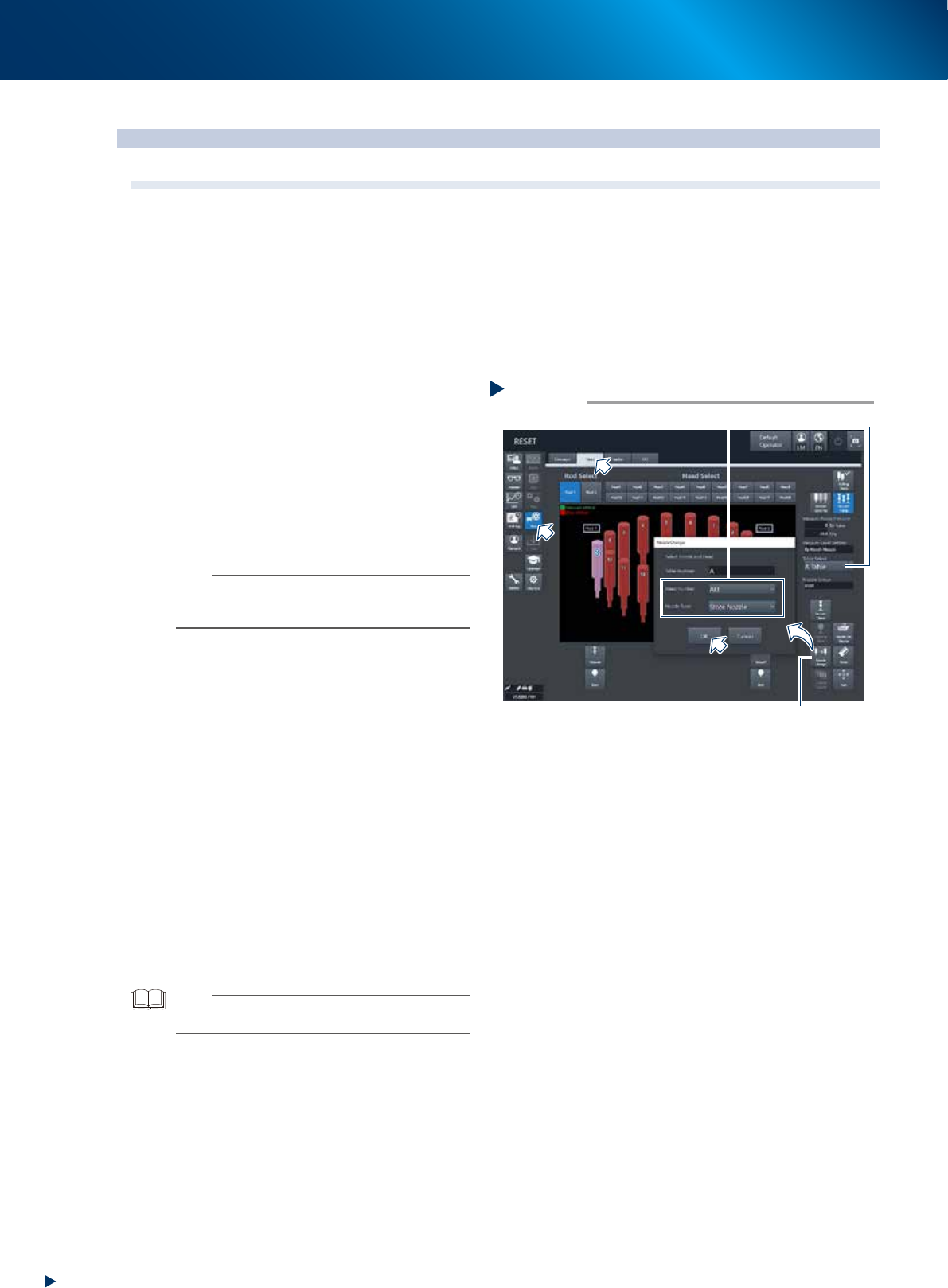
1. Open the [Unit] - [Head] screen.
2. Select desired head unit from "Table Select".
3. Press the [Nozzle Change] button.
4. Select "ALL" for "Head Number" and select
"Store Nozzle" for "Nozzle Type" on the
"Nozzle Change" screen.
5. Press the [OK] button to return all nozzles to
the nozzle station.
n
NOTE
If the machine is not equipped with a nozzle station, press
the emergency stop button and then detach the nozzles
manually.
2
Prepare for work.
e
1. Remove all items sensitive to magnetic fields
such as wristwatches and magnetic ID cards.
2. Press the emergency stop button and detach
the feeder exchange carriage. Then open
the machine safety cover.
3. Move the head unit to convenient position to
work and place a square cloth beneath the
head unit.
3
Detach all filters.
See Step 3 of "2.4.1 Inspecting and replacing
the air filters" to detach all filters.
4
Clean and lubricate all spools.
See "6.2.3 Cleaning/lubricating the vacuum
selector (spool)" above to clean and lubricate
all spools.
TIP
It is not necessary to return detached spools to the original
positions.
Step 1
[Nozzle Change] button
Table Select
Select “ALL” for Head Number, “Store Nozzle”for Nozzle Type
Storing nozzle
54326-KMX-00
8. Others
3-69
Chapter 3 Periodic maintenance items
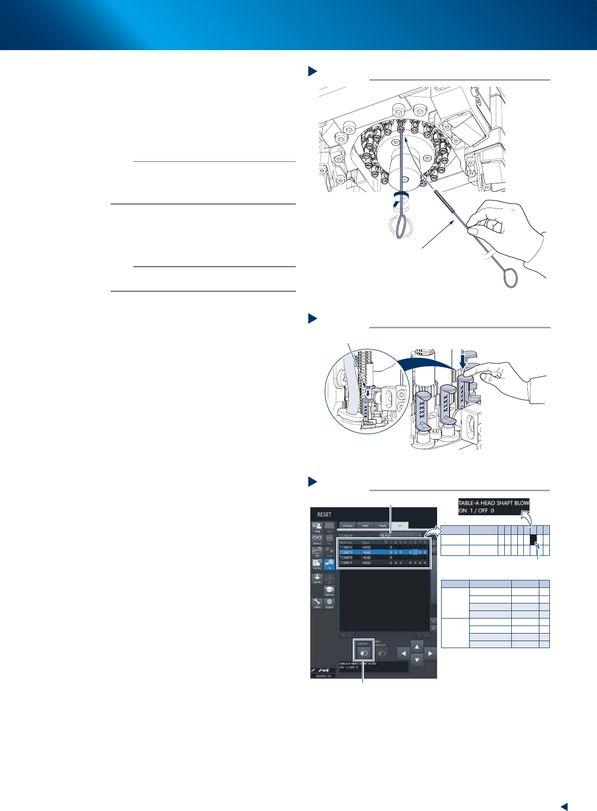
5
Preclean inside of shaft with brush to
remove dirt or foreign objects easily.
1. Insert spline brush (KMB-M3858-00X) deeply
into the nozzle shaft. Turn it left/right
several times.
2. Clean the rest of spline shaft insides with the
same procedures above.
n
NOTE
• Do not hold edge of spline brush. Doing so may bend
the brush.
• A spline brush can clean all 18 heads of RS head unit,
although this may vary depending on dirt.
6
Set all spools of target head unit to the
"blow position" by lowering them to the
downmost by hand.
n
NOTE
Lower the spool to prevent the sudden high pressure blow
at Step 7.
7
Turn OFF the head shaft blow valve, and
ON the vacuum pressure select valve.
1. See "Blow air path on RS head unit" below
to check the head unit and rod number to be
blown.
2. Change to the [Unit] - [I/O] screen, the
select "Head" for [Output].
3. Confirm that the both I/O of "Z1 blow
valve" amd "Z2 blow valve" of head unit
those confirmed at item 1. above are set as
"0".
4. Press the I/O of head shaft blow of target
head unit, then turn OFF the "head shaft
blow" valve (1 to 0) by pressing the [ON/
OFF] button displayed at the bottom of
screen.
5. Turn ON the "Vacuum pressure selection" (0
to 1) of the target head unit as same
procedure.
Precleaning inside of shaft
Step 5
Spline brush
533H9-KMX-00
Moving down spool
Step 6
Move the spool downmost
533J1-KMX-10
Turning head shaft blow OFF, head vacuum switch ON
Step 7
Select head
Head unit
Valve
Address
Output
A (Table A)
Z1 Blow Valve A
Z2 Blow Valve A
HEAD SHAFT BLOW
HEAD VAC_SWITCH
Z1 Blow Valve B
Z2 Blow Valve B
HEAD SHAFT BLOW
HEAD VAC_SWITCH
T130071 0 0
0
0
0
0
0
T130071 1
1
1
T130071
T130071
2
3
B (Table B)
T230071 0
T230071 1
T230071
T230071 2
3
-
-
-
-
-
-
-
-
[ON/OFF] button
Click to select
* Z1:Rod 1
Z2:Rod 2
Address
T130071
T230071
Type
HEAD
HEAD
7
0
0
6
0
0
5
0
0
4 3
0
0
2
0
0
1
0
0
0
0
0
54328-KMX-00
8. Others
3-70
Chapter 3 Periodic maintenance items
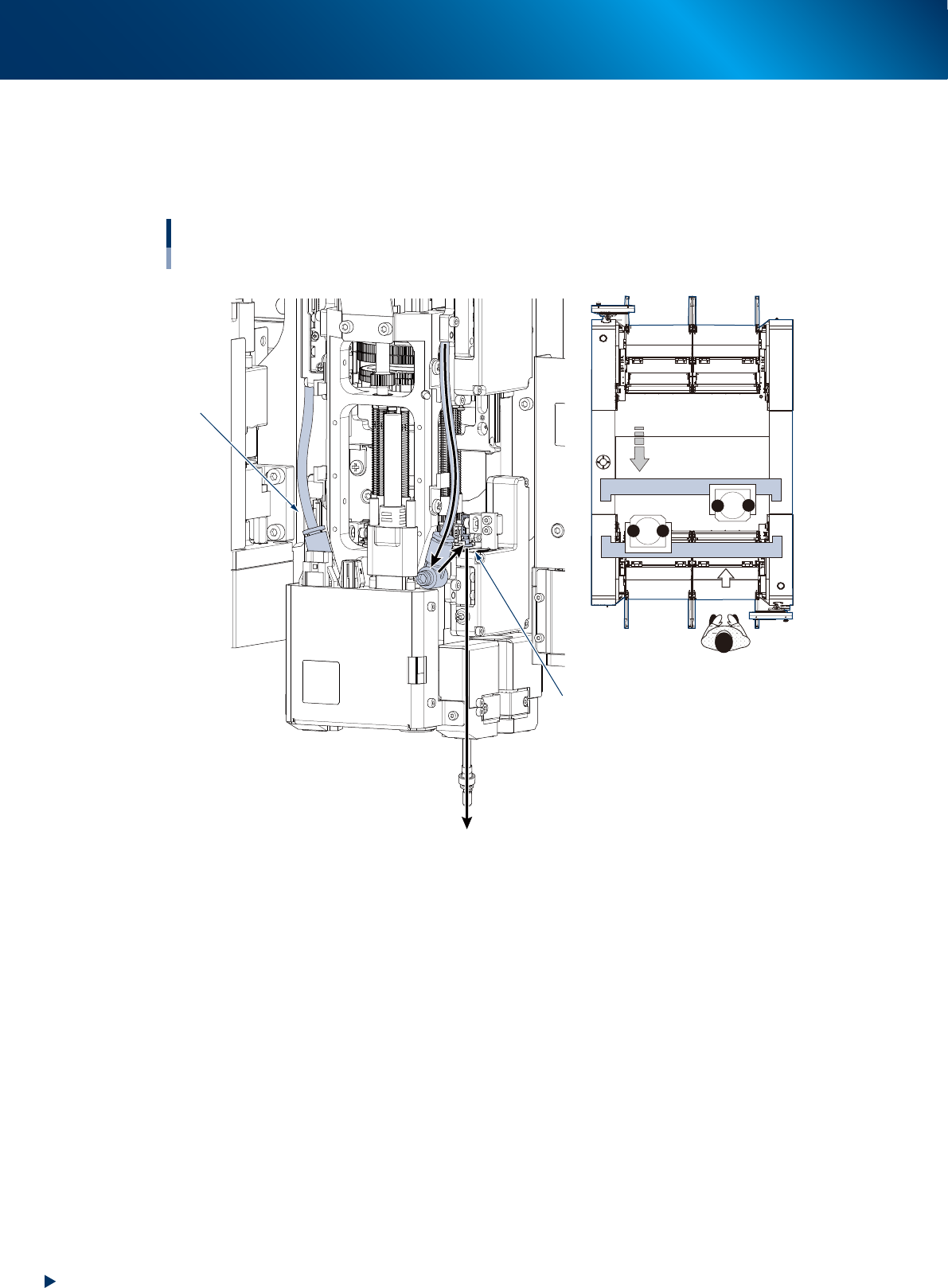
►
Blow air path on RS head unit
Seen RS head unit from front, the air hose on the right is called "Rod 1 air line". The other side is called
"Rod 2 air line". When using blow air for RS head maintenance, select a rod based on checking the
head unit to be maintained, worker's position, and rod position.
Positions of head unit and rod
Example: Head unit B
Rod 1 air line
Rod 2 side
1
2
1
2
B
A
Move head unit.
↓ Machine front
533J0-KMX-00