YRM20_Mainte_E.pdf - 第118页
5. 1-year maintenance 3-51 Chapter 3 Periodic maintenance items 8 Apply specified grease (NSL ) uniforml y by hand to the sur face and grooves of ball sc re w and the surf ace of hexagon spline . 9 Apply grease to the gui…
5. 1-year maintenance
3-50
Chapter 3 Periodic maintenance items
4
e
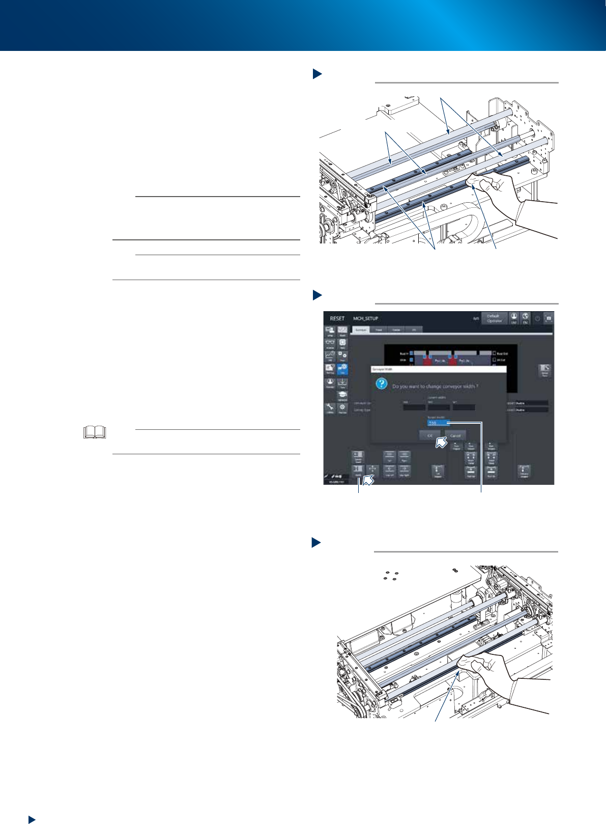
Clean each section of W-axis and U-axis.
1. Press the emergency stop button and detach
the feeder exchange carriage. Then open
the machine safety cover.
2. Remove all items sensitive to magnetic fields
such as wristwatches and magnetic ID cards.
3. Wipe away old grease or dirt from all over
the 8 ball screws, 6 guides, and 4 hexagon
spline of W-axis and U-axis, using a lint-free
cloth or similar.
n
NOTE
Carefully wipe the lead grooves of ball screw and the
grooves of guide rail during cleaning. Also, make sure
that no dust, lint and debris remain on the ball screw and
guide.
n
NOTE
See also "Chapter 4 Lubricating points" for the positions
and numbers of ball screw, guide, and hexagon spline.
5
Maximize the conveyor width.
1. Close the machine safety cover and attach
the feeder exchange carriage. Then release
the emergency stop.
2. Press the [Conveyor width] button to display
the [Conveyor width] screen.
3. Input the maximum width of "510mm" of the
dual stage type machine in the "Changed
conveyor width" field and press the [OK]
button. Then the conveyor width is changed
to the specified.
TIP
The push up unit lowers automatically by changing the
conveyor width.
6
Raise the push up unit by the same
procedure of Step 3.
e
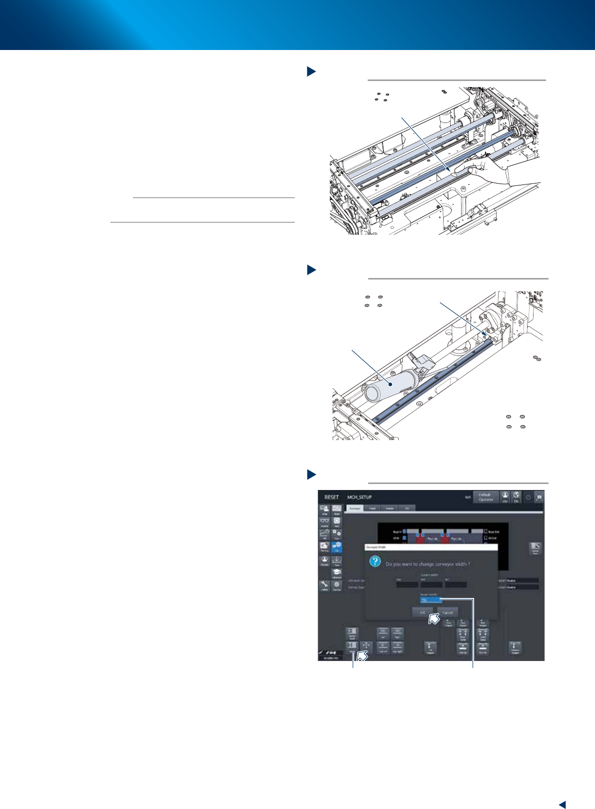
7
Wipe away the remained grease.
1. Press the emergency stop button and detach
the feeder exchange carriage. Then open
the machine safety cover.
2. Wipe the area not accomplished at Step 4
using a lint-free cloth or similar.
Step 4
Cleaning the W-axis and U-axis
Ball screws
Guide
Hexagon spline shaft
Lint-free cloth
53369-KMX-10
Step 7
Cleaning the W-axis and U-axis 2
Wipe the remained area
53370-KMX-10
Maximizing the conveyor width
Step 5
[Width] button
Input “510mm”
54308-KMX-00
5. 1-year maintenance
3-51
Chapter 3 Periodic maintenance items
8
Apply specified grease (NSL) uniformly
by hand to the surface and grooves of
ball screw and the surface of hexagon
spline.
9
Apply grease to the guide using a grease
gun.
Inject the specified grease (NSL) through the
guide grease nipple until the grease excesses
from the gap of block.
n
NOTE
See also "Chapter 4 Lubricating points" for the positions
and numbers of guide grease nipple.
0
Minimize the conveyor width.
1. Close the machine safety cover and attach
the feeder exchange carriage. Then release
the emergency stop.
2. Press the [Conveyor width] button to display
the [Conveyor width] screen.
3. Input the minimum width of "50mm" in the
"Changed conveyor width" field and press
the [OK] button. Then the conveyor width is
changed to the specified.
q
Raise the push up unit by the same
procedure of Step 3.
e
w
Apply grease to other ball screw and
hexagon spline.
1. Press the emergency stop button and detach
the feeder exchange carriage. Then open
the machine safety cover.
2. Apply specified grease (NSL) uniformly by
hand to the surface and grooves of ball
screw and the surface of hexagon spline,
not yet accomplished at Step 8.
e
Spread grease.
1. Close the machine safety cover and attach
the feeder exchange carriage. Then release
the emergency stop.
2. Repeat Step 5 and Step 2 to move the
conveyor from maximum to minimum width
for some times.
e
r
Wipe away the excess grease.
1. Press the emergency stop button and detach
the feeder exchange carriage. Then open
the machine safety cover.
2. Wipe away the excess grease from the ends
of hexagon spline and the grooves of ball
screw and guide, using a lint-free cloth or
similar.
Step 8
Lubricating the ball screw and hexagon spline
Spread uniformly
53371-KMX-10
Step 9
Lubricating the guide
Grease nipple
Grease gun with
a 30° bent type nozzle
53372-KMX-10
Minimizing the conveyor width
Step 10
[Width] button
Input “50mm”
54309-KMX-00
5. 1-year maintenance
3-52
Chapter 3 Periodic maintenance items
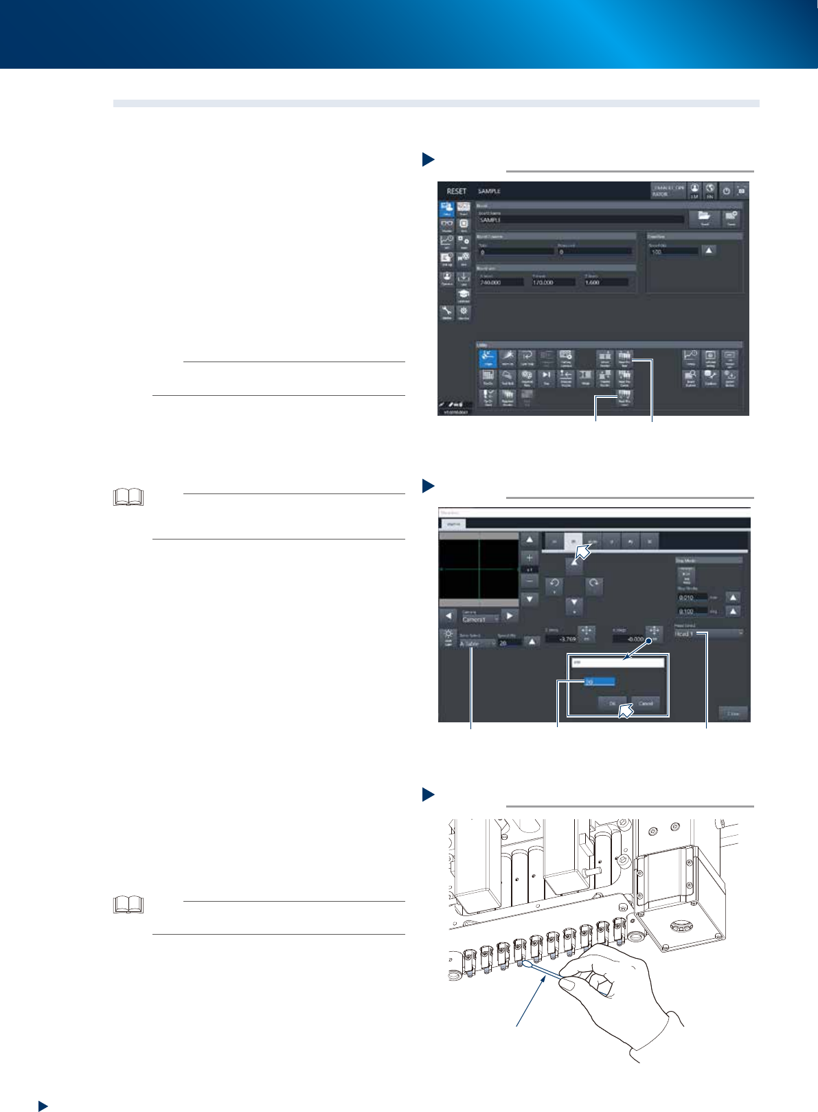
5.4 HM head: cleaning the shaft tip
When the dust or dirt is found at "3.1.4 Inspecting shaft tips", clean the shaft tips as the following
procedure.
1
Detach all the nozzles.
When a nozzle station is equipped:
1. Open the [Unit] - [Head] screen.
2. Select any head unit from "Table Select".
3. Press the [Nozzle Change] button.
4. Select "ALL" for "Head Number" and select
"Store Nozzle" for "Nozzle Type" on the
"Nozzle Change" screen.
5. Press the [OK] button to return all nozzles to
the nozzle station.
n
NOTE
When the nozzle station is not equipped, open the
machine safety cover and detach the nozzles by hand.
2
Move the head unit to working position.
Press the [Head Pos. Front] or [Head Pos. Rear]
button on the "Utility" field to move the head
unit to convenient position to work.
TIP
As to the 2-beam type machine, moving the front head unit
to rear and the rear head unit to front facilitate your access
to the head unit.
3
Turn the head unit 90-degree.
1. Press the [Move axis] button on the [Unit]
- [Conveyor] screen and select "ZR" tab.
2. Select any head unit from the "Table Select"
field.
3. Select "Head 1" from the pull-down menu of
the "Head Select" field.
4. Press the [PTP] button of "R (deg)" and input
90-degree, then press the [OK] button. The
head direction from no.1 to no.5 change.
Also, the direction of head unit no.6 to
no.10 can be changed by selecting the
head 6 and inputing 90-degree.
e
5. Press the emergency stop button and detach
the feeder exchange carriage. Then open
the machine safety cover.
4
Clean the shaft tip using a cotton swab
applied a few drops of ethanol. Twist
the swab tip lightly to make it slim upon
cleaning the side of shaft.
TIP
When the cleaning has some trouble, push down the
Z-axis joint block by hand to clean well.
Moving the head unit
Step 2
[Head Pos. Front] button [Head Pos. Rear] button
54317-KMX-00
Turning the head unit
Step 3
Input 90 degrees Select headSelect table
54318-KMX-00
Cleaning the shaft tip
Step 4
Cotton swab
53399-KMX-00