YRM20_Mainte_E.pdf - 第137页
8. Others 3-70 Chapter 3 Periodic maintenance items ► Blow air path on RS head unit Seen RS head unit from front, the air hose on the right is called "Rod 1 air line". The other side is called "Rod 2 air l…
8. Others
3-69
Chapter 3 Periodic maintenance items
5
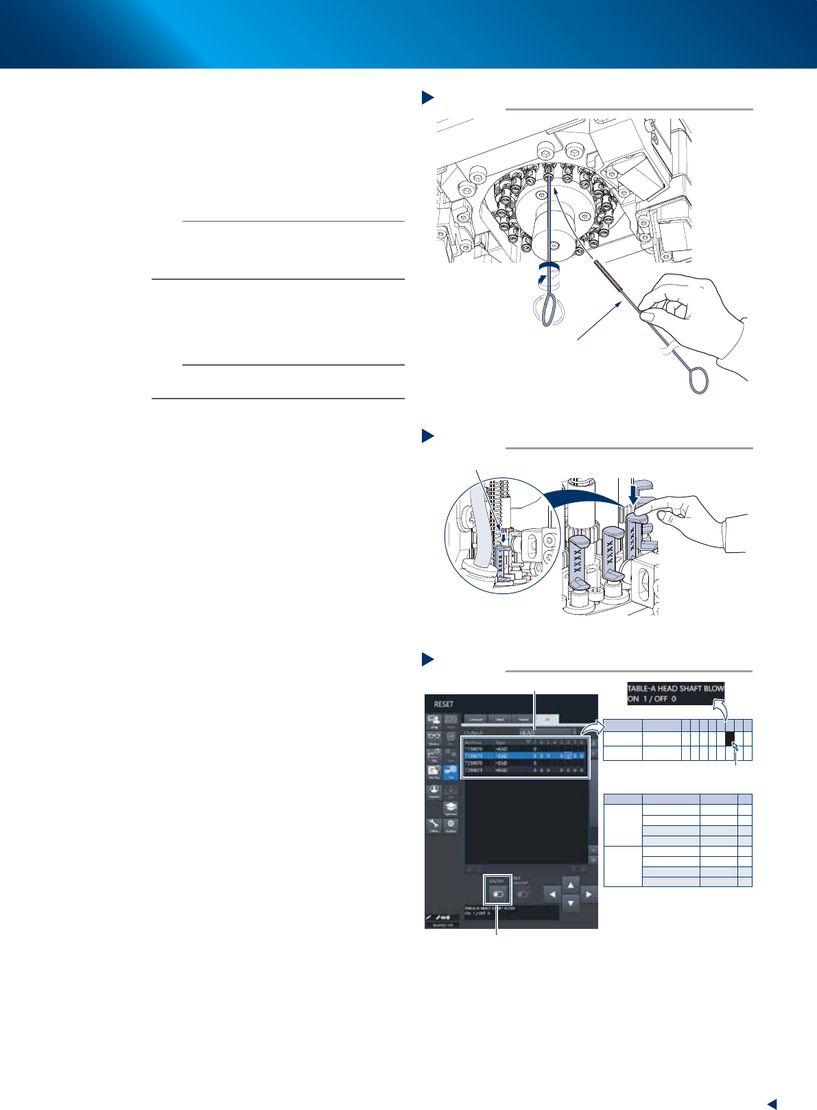
Preclean inside of shaft with brush to
remove dirt or foreign objects easily.
1. Insert spline brush (KMB-M3858-00X) deeply
into the nozzle shaft. Turn it left/right
several times.
2. Clean the rest of spline shaft insides with the
same procedures above.
n
NOTE
• Do not hold edge of spline brush. Doing so may bend
the brush.
• A spline brush can clean all 18 heads of RS head unit,
although this may vary depending on dirt.
6
Set all spools of target head unit to the
"blow position" by lowering them to the
downmost by hand.
n
NOTE
Lower the spool to prevent the sudden high pressure blow
at Step 7.
7
Turn OFF the head shaft blow valve, and
ON the vacuum pressure select valve.
1. See "Blow air path on RS head unit" below
to check the head unit and rod number to be
blown.
2. Change to the [Unit] - [I/O] screen, the
select "Head" for [Output].
3. Confirm that the both I/O of "Z1 blow
valve" amd "Z2 blow valve" of head unit
those confirmed at item 1. above are set as
"0".
4. Press the I/O of head shaft blow of target
head unit, then turn OFF the "head shaft
blow" valve (1 to 0) by pressing the [ON/
OFF] button displayed at the bottom of
screen.
5. Turn ON the "Vacuum pressure selection" (0
to 1) of the target head unit as same
procedure.
Precleaning inside of shaft
Step 5
Spline brush
533H9-KMX-00
Moving down spool
Step 6
Move the spool downmost
533J1-KMX-10
Turning head shaft blow OFF, head vacuum switch ON
Step 7
Select head
Head unit
Valve
Address
Output
A (Table A)
Z1 Blow Valve A
Z2 Blow Valve A
HEAD SHAFT BLOW
HEAD VAC_SWITCH
Z1 Blow Valve B
Z2 Blow Valve B
HEAD SHAFT BLOW
HEAD VAC_SWITCH
T130071 0 0
0
0
0
0
0
T130071 1
1
1
T130071
T130071
2
3
B (Table B)
T230071 0
T230071 1
T230071
T230071 2
3
-
-
-
-
-
-
-
-
[ON/OFF] button
Click to select
* Z1:Rod 1
Z2:Rod 2
Address
T130071
T230071
Type
HEAD
HEAD
7
0
0
6
0
0
5
0
0
4 3
0
0
2
0
0
1
0
0
0
0
0
54328-KMX-00
8. Others
3-70
Chapter 3 Periodic maintenance items
►
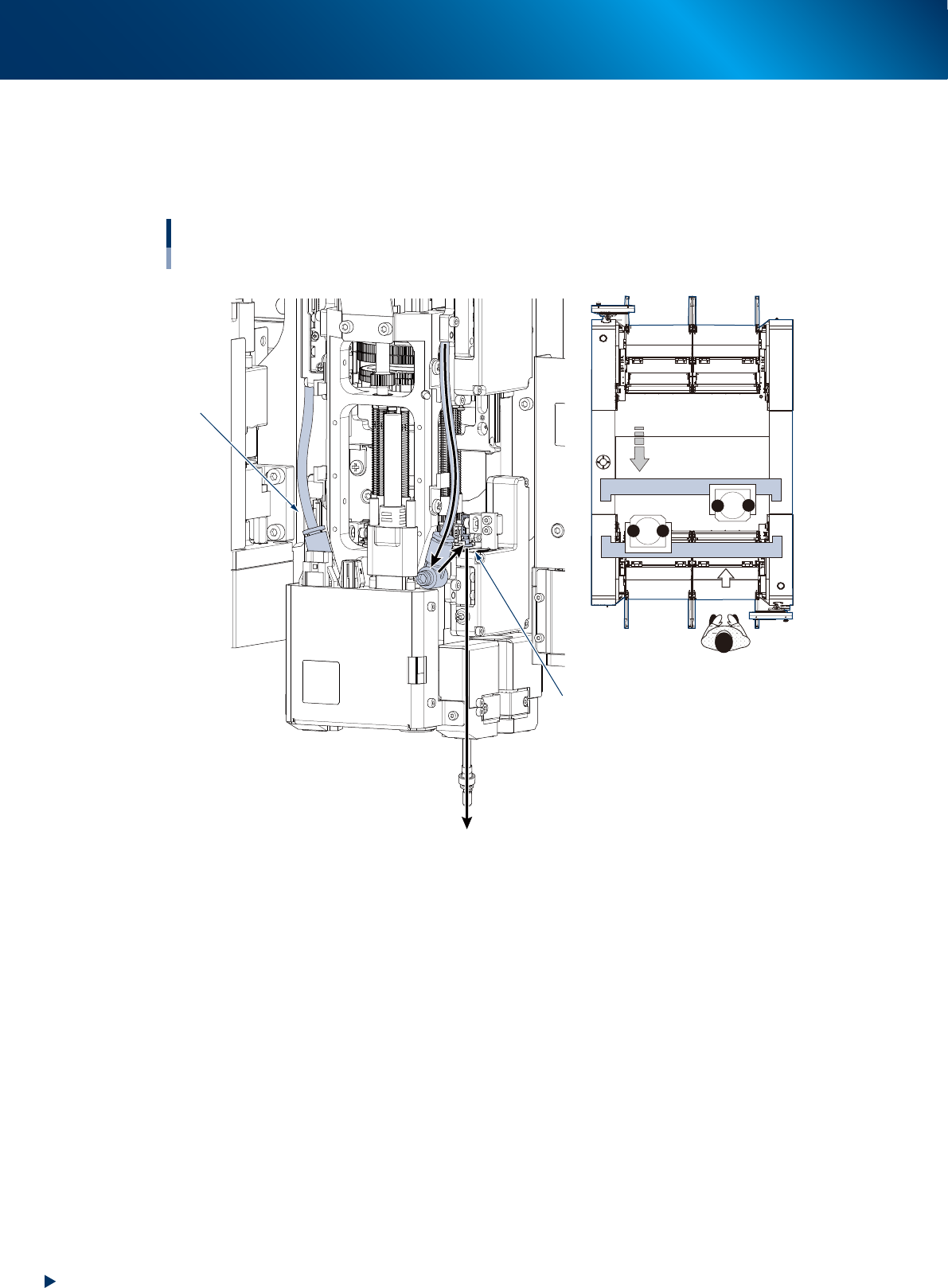
Blow air path on RS head unit
Seen RS head unit from front, the air hose on the right is called "Rod 1 air line". The other side is called
"Rod 2 air line". When using blow air for RS head maintenance, select a rod based on checking the
head unit to be maintained, worker's position, and rod position.
Positions of head unit and rod
Example: Head unit B
Rod 1 air line
Rod 2 side
1
2
1
2
B
A
Move head unit.
↓ Machine front
533J0-KMX-00
8. Others
3-71
Chapter 3 Periodic maintenance items
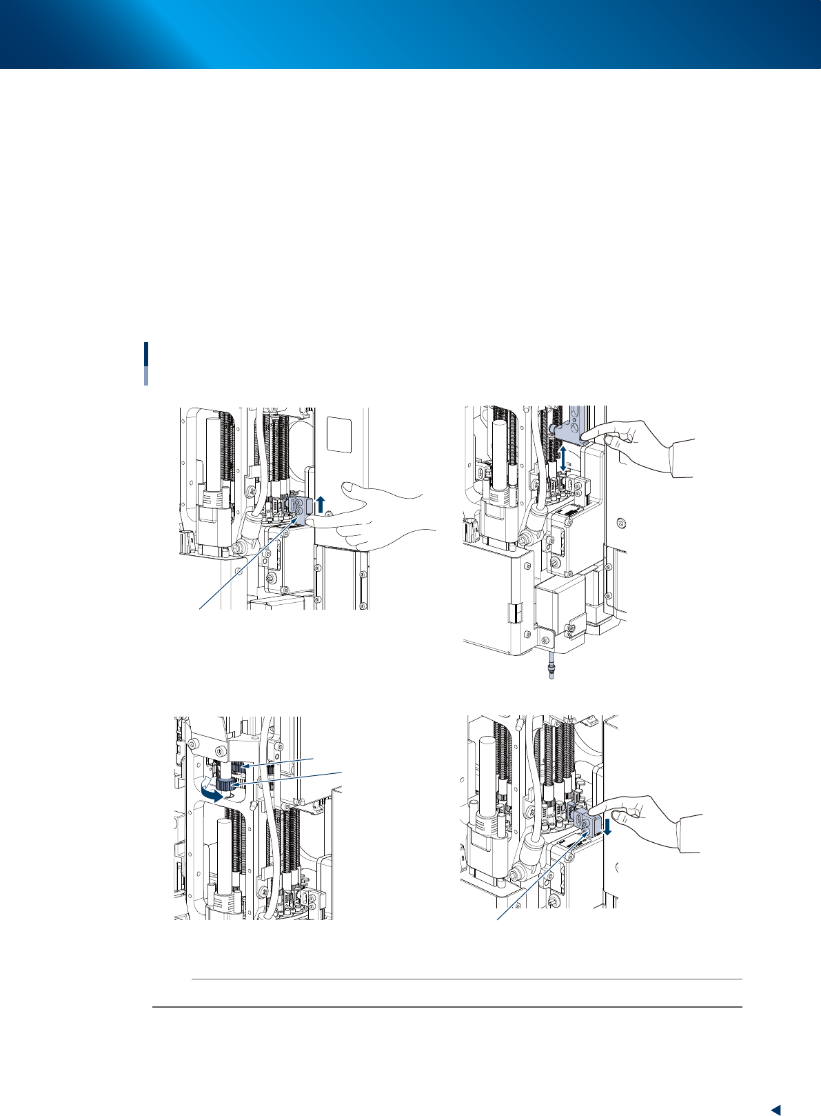
8
Blow inside the shaft as follows:
1. Raise the target rod side of V-axis, then the target spool raises and blows with high pressure
inside the nozzle shaft.
2. Keep this condition and push Z-axis on its target rod for some times using finger to move
vertically the nozzle shaft installed in its lower area.
3. Hold N-axis gear by hand and turn R-axis gear, then rotate the nozzle shaft approximately 120
degrees.
4. Keep this condition and push Z-axis on its target rod for some times using finger to move
vertically the nozzle shaft installed in its lower area.
5. Repeat the procedures above 3 and 4.
6. Lower V-axis using finger to stop high pressure blow.
7. Turn N-axis to rotate the rotary, then repeat the procedures of 1 to 6 for all the heads.
High pressure blow inside of nozzle shaft
Lower V-axis to stop high pressure blow
Turn R-axis gear
Hold N-axis gear by hand
Raise V-axis to blow with high pressure
1
8- 28-
3
8-
6
8-
4
8-
533J2-KMX-00
n
NOTE
It requires approx. 30 seconds to blow per head. If dirt cannot be removed, blow a little longer.