YRM20_Mainte_E.pdf - 第149页
Chapt er 5 Ho w t o replac e consumable p art s Contents 1. Nozzles 5- 1 1. 1 Replacing nozzle tip and spring 5-1 1.2 Replacing O-ring at nozzle tip 5-2 2. Nozzle leaf springs 5-3 2.1 HM hea d : Replacing nozzle leaf spr…
2. Lubricating poits/schedule (Main machine)
4-8
Chapter 4 Lubricating points
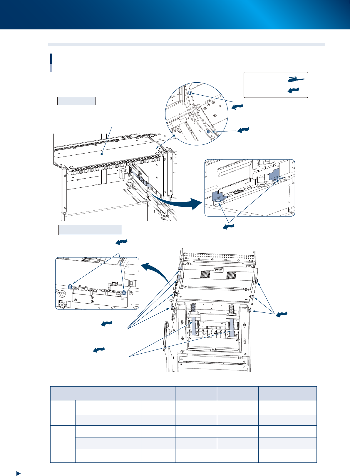
2.6 Feeder exchange carriage
4 Cam followers
3 Cam followers
Carriage clamp section
Carraige eleveting shaft section
Carriage positioning section
Feeder exchange carriage lubricating points (carriage side and main machine side)
Upper cover, Cam follower, Carriage elevating shaft section or similar
Main machine side
Feeder exchange carriage side
Positioning pin
Upper cover side positioning hole
Upper cover
Upper cover positioning section
Carriage
positioning holes
Grease gun:
Manual lubrication:
53509-KMX-00
Lubricating section Grease
Lubricating
point
Interval Procedure
Main
machine
side
Upper cover positioning
section
NSL grease 4 per 1 machine Every 3 months Manual lubrication
Carriage positioning hole NSL grease 8 per 1 machine Monthly Manual lubrication
Carriage
side
Carriage positioning pin NSL grease 2 per 1 carriage Monthly Manual lubrication
Cam follower NSL grease 7 per 1 carriage Monthly Manual lubrication
Carriage elevating shaft
section
NSL grease 2 per 1 carriage Yearly or more Manual lubrication

Chapter 5 How to replace consumable parts
Contents
1. Nozzles 5-1
1.1 Replacing nozzle tip and spring 5-1
1.2 Replacing O-ring at nozzle tip 5-2
2. Nozzle leaf springs 5-3
2.1 HM head
:
Replacing nozzle leaf springs 5-3
3. Head unit 5-5
3.1 HM head: Replacing the valves 5-5
4. Conveyor unit 5-6
4.1 Replacing the conveyor belt 5-6
4.2 Replacing the valves at conveyor section 5-14
5. Base 5-16
5.1 Replacing carriage clamp valve 5-16
1. Nozzles
5-1
Chapter 5 How to replace consumable parts
1. Nozzles
When the nozzle tip or O-ring is worn out due to long-term use, pickup and placement errors are
likely to occur. If the spring action of a nozzle is not smooth even after cleaning and lubricating the
nozzle, the internal spring may need to be replaced.
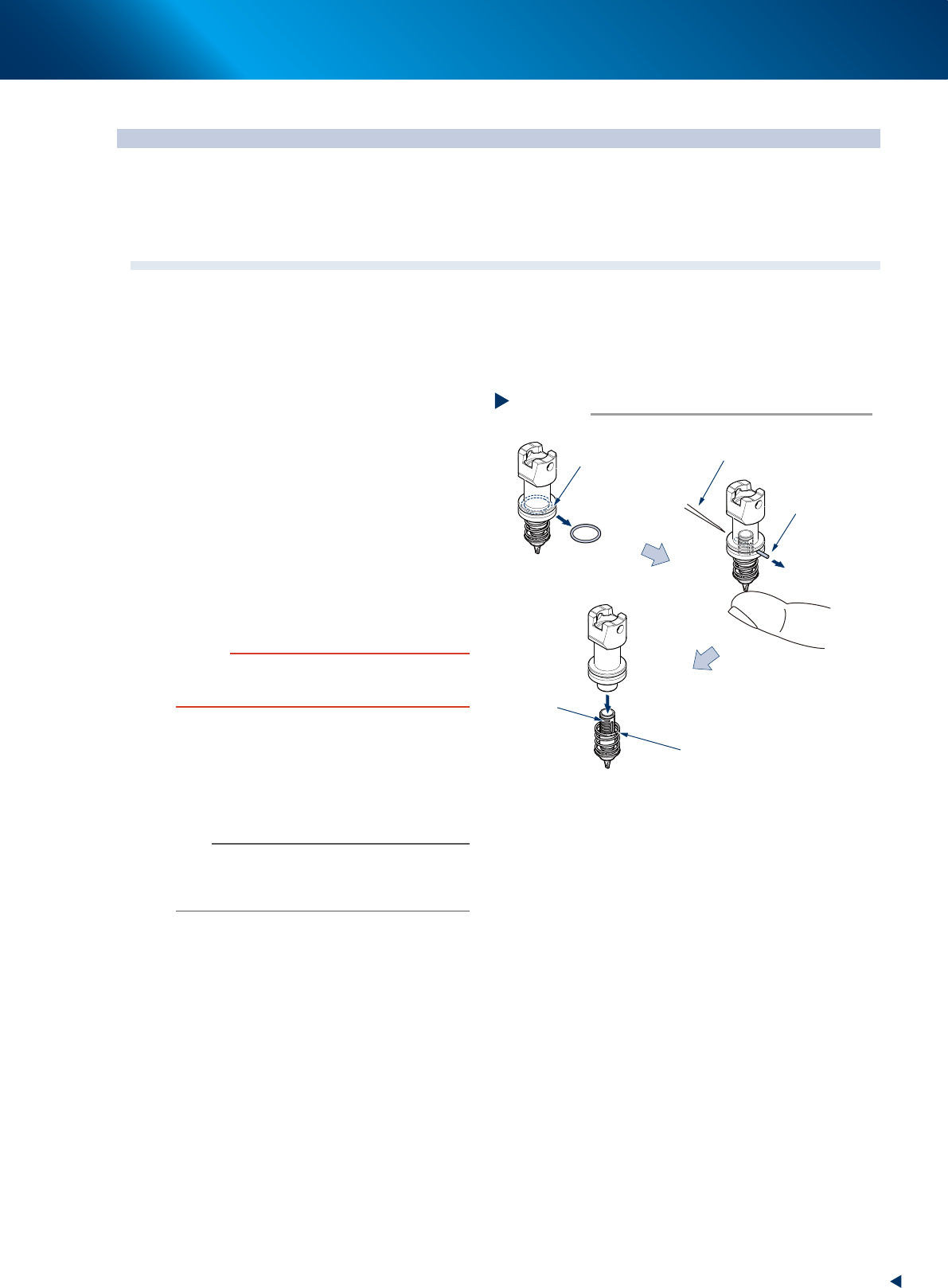
1.1 Replacing nozzle tip and spring
e
1
Detach the nozzle.
1. Press the emergency stop button and open
the machine safety cover.
2. Detach relevant nozzle manually.
2
Replace the nozzle tip and spring.
1. Detach the O-ring from the nozzle.
2. Push out the pin using some needle-like
material while pushing up lightly the nozzle
tip.
3. The internal spring comes out as the nozzle
tip is detached, then replace the nozzle tip
and/or spring.
4. Mount the nozzle tip using a pin. Insert a
pin to the position which is aligning to the
nozzle tip inserting position.
5. Attach the O-ring. When it is worn or
deteriorated, replace it.
c
CAUTION
See "2.1.3 Common to all models" in Chapter 1 to check
that nozzle marking (example: 8104A, 8105A) impressed
on nozzle body matches type No. of nozzle tip.
3
Lubricate nozzle slide section referring
to "1.2.1 Cleaning and lubricating
nozzle sliding section" in Chapter 3.
4
Return nozzles to the original heads.
n
NOTE
Be sure to return the nozzle you have detached to its
mating head. When the nozzle has been detached from
the nozzle station (option), return it correctly to the storage
position where you have detached the nozzle.
Pull out
Pull out
Push out with a tweezer like material
Replacing nozzle tip
Step 2
O-ring
Pin
Spring
Tip part
53500-KMX-00