YRM20_Mainte_E.pdf - 第115页
5. 1-year maintenance 3-48 Chapter 3 Periodic maintenance items 9 Attach board clamp p late. 1. Attach the board clamp board to the origina l position. Mount it b y tightening the board mounting bolt using a hexagon w re…
5. 1-year maintenance
3-47
Chapter 3 Periodic maintenance items
6
Check the status of conveyor belt
whether there are no worn or fraying
on the transfer surface of detached belt.
When the many worn or fraying are
found, replace the conveyor belt
referring "Chapter 5 How to replace
consumable parts".
7
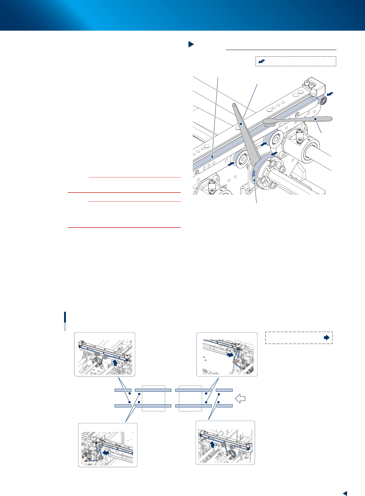
Clean the belt guide section and pulley.
1. Use a vacuum assembly (option) to suction
the belt wear debris on the belt guides and
sensors, etc.
2. Use a plastic spatula or similar tool to
remove the belt wear debris adhering to the
outer peripheral surface of the pulleys.
3. Use a brush or similar tool to remove the
belt wear debris caught in the belt guides.
53366-KMX-00
c
CAUTION
Use a plastic spatula and brush to avoid scratching the
pulleys and guides.
c
CAUTION
Do not use a solvent (IPA, etc.) unless the guides and
pulleys are excessively dirty. If using ethanol, be careful
not to spill the ethanol on the bearing in the pulleys during
cleaning.
8
Reattach the belt.
1. Temporarily place the belt on the pulley.
2. Move the bracket (pulley for CV1 and CV4) to the position marked in Step 4 and tighten the mounting bolt
by the following tightening torque. Be careful not to excess the specified value.
• Pulley bracket mounting bolt : 3.8 N•m
• Pulley mounting bolt : 5.5 N•m
3. If there is a slack in the belt, adjust the position of bracket (pulley for CV1 and CV4) to apply proper tension.
The tension measuring position and the specified tension value is shown below. Use a tension gauge as
necessary.
Tension standard: 190 - 220 Hz
Tension standard: 190 - 220 Hz
Tension standard: 400 - 450 Hz
Tension standard: 400 - 450 Hz
CV1CV2CV3CV4
Conveyor belt
Tension measuring position and specified tension value
Tension measuring position:
Transfer
direction
53367-KMX-10
Cleaning the belt guide section and pulley
Step 7
Plastic spatula
Belt guide section
Adhering belt wear debris
Brush
: Outer peripheral surface of pulley
5. 1-year maintenance
3-48
Chapter 3 Periodic maintenance items
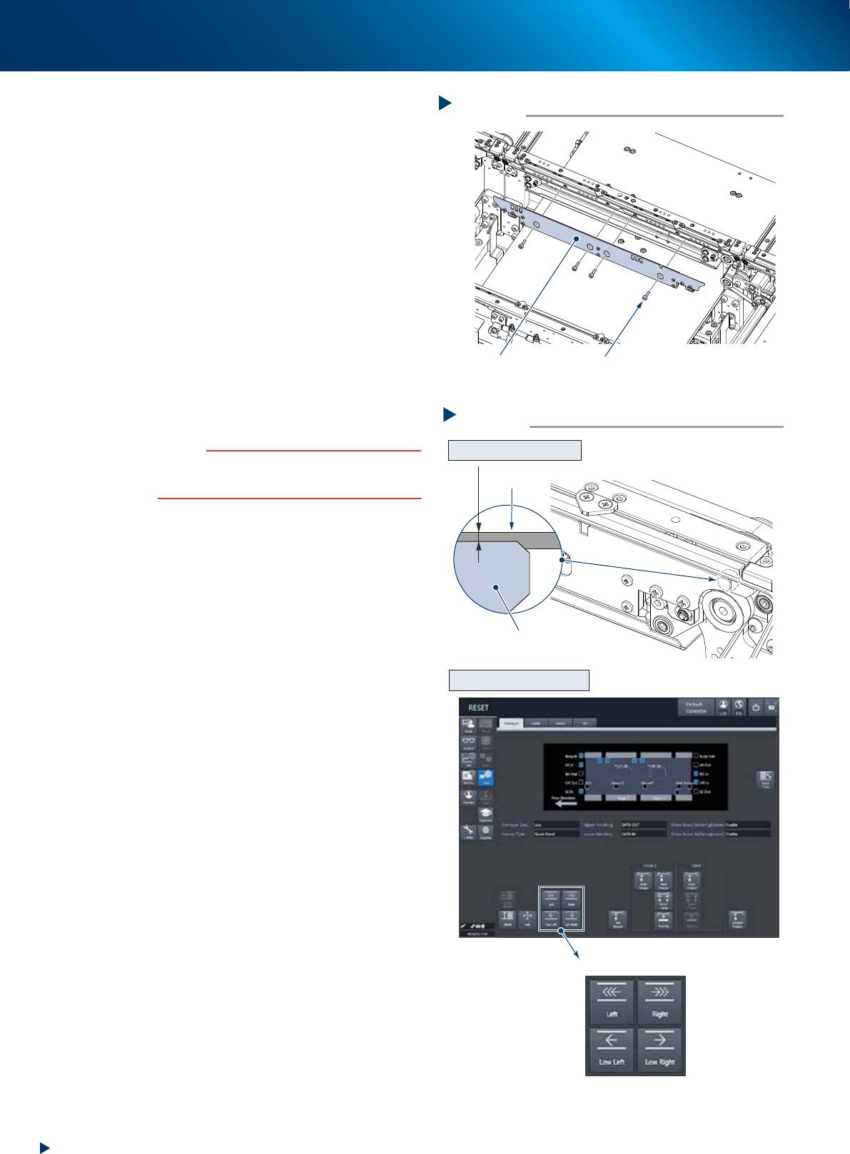
9
Attach board clamp plate.
1. Attach the board clamp board to the original
position. Mount it by tightening the board
mounting bolt using a hexagon wrench (3).
2. Retrieve a square cloth.
0
Check that the conveyor belt is attached
correctly.
1. Check that the upper surface of board clamp
is in a position at approx. 0.5mm lower
than that of the belt.
2. Attach the upper cover, close the machine
safety cover and attach the feeder exchange
carriage. Then release the emergency stop.
3. Press the [Conveyor drive] button on the
[Unit] - [Conveyor] screen to run the
conveyor belt and check its motion.
4. When the conveyor belt does not run evenly
or there is a slack in the belt, adjust again
the position of bracket (pulley for CV1 and
CV4).
c
CAUTION
When the upper surfaces of belt and board clamp are
almost even, the board transfer error may occur. Contact
your sales representative as such occasion.
Attaching the board clamp plate
Step 9
Board clamp plate
Mounting bolt
53368-KMX-00
Checking the attached conveyor belt
Step 10
[Conveyor drive] button
Checking the attached status
Checking the conveyor motion
0.5 mm
Board clamp plate
Belt
54305-KMX-00
5. 1-year maintenance
3-49
Chapter 3 Periodic maintenance items
5.3
Cleaning/lubricating the W-axis and U-axis
The once-a-year cleaning and lubricating for ball screw, guide, and hexagon spline of W-axis and U-axis is
required. See also "Chapter 4 Lubricating points" for details.
1
Read any board data.
TIP
Moving the push up unit of both stage 1 and stage 2 are
available by reading board data.
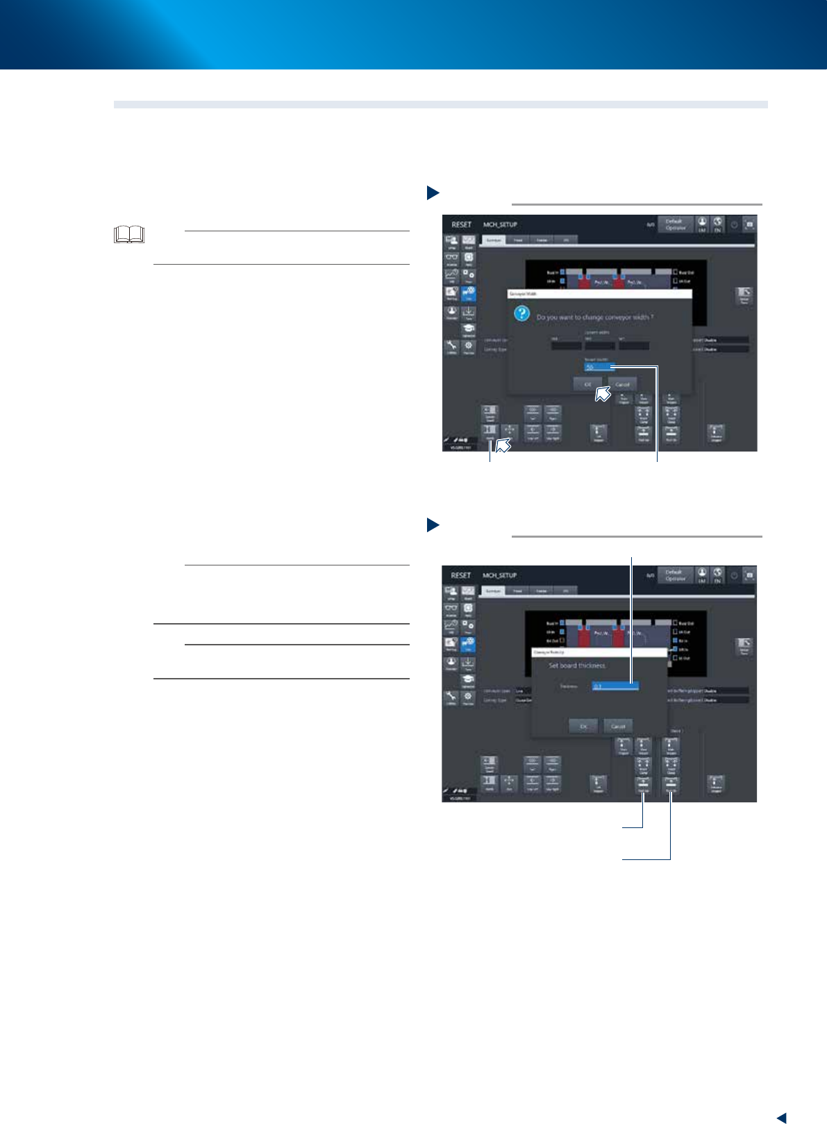
2
Set the conveyor width to the minimum.
1. Press the [Width] button on the [Unit] -
[Conveyor] screen to display the [Conveyor
width] screen.
2. Input the minimum width of "50mm" in the
"Target width" field and press the [OK]
button. Then the conveyor width is changed
to the specified.
3
Raise the push up unit.
1. Press the [Push up] button to display the
"Conveyor Pushup" screen.
2. Input "0.1 mm" in the "Board thickness" field
and press the [OK] button. Then the push up
unit raises.
3. Raise the push up units of both stage 1 and
stage 2 by the procedure above.
n
NOTE
When the board size X of the board data selected at Step
1 excesses 380mm, the [Push up] button of upstream side
is grayed-out. The upstream push up unit raises engaging
with the raise of downstream push up unit.
n
NOTE
The access to the guide and ball screw of U-axis become
easier by raising the push up units.
Minimizing the conveyor width
Step 2
[Width] button Input “50mm”
54306-KMX-00
Raising the push up unit
Step 3
Stage 1
[Push Up] button
Input “0.1mm”
Stage 2
[Push Up] button
54307-KMX-00