YRM20_Mainte_E.pdf - 第162页
4. Conveyor unit 5-13 Chapter 5 How to replace consumable parts 9 Attach the boar d clam p plate. 1. Attach the boa rd clamp to its origin al position. Mount it b y tightening the bolts using a hexagon wrench (3). 2. Ret…
4. Conveyor unit
5-12
Chapter 5 How to replace consumable parts
8
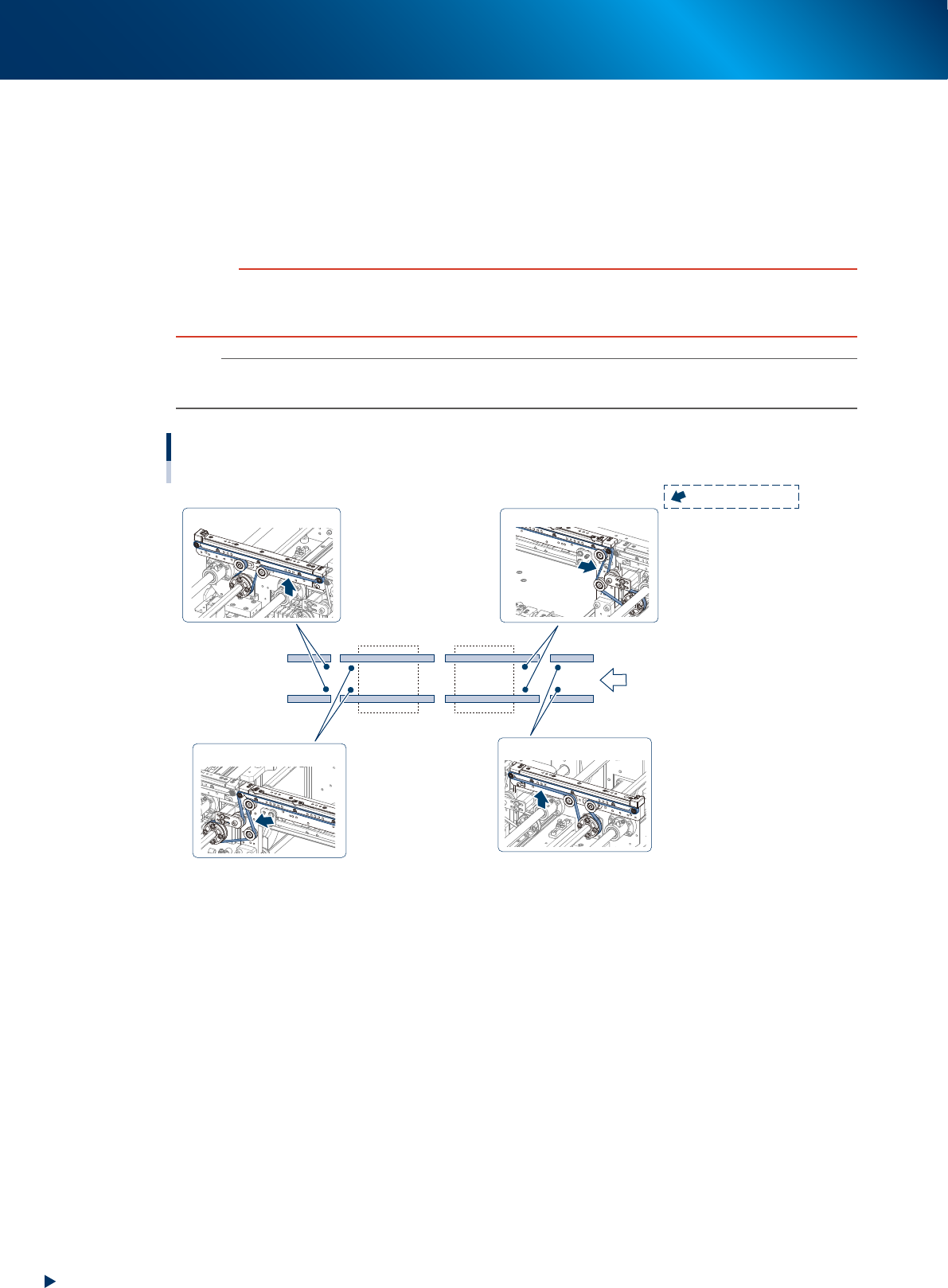
Replace the conveyor belt.
1. Hang a new conveyor belt temporarily to the pulley.
2. Insert the shaft to the belt drive pulley.
3. Fix the shaft by tightening the mounting bolt.
4. Move the pulley (for CV2, bracket) to the position marked at Step 4 and attach mounting bolt.
5. If there is a slack on the belt, adjust the pulley (for CV2, bracket) position to tension the belt.
c
CAUTION
The followings are tightening torques of the pulley/bracket mounting bolts. Do not tighten the bolt excessively.
Pulley mounting bolt : 5.5 N•m.
Bracket mounting bolt : 3.8 N•m.
n
NOTE
The tension measurement positions of this machine and the tension standards are as below.
Adjust with tension meter as needed.
Tension standard: 190 - 220 Hz
Tension standard: 190 - 220 Hz
Tension standard: 400 - 450 Hz
Tension standard: 400 - 450 Hz
CV1CV2CV3CV4
Tension measuring position and specified tension
Transfer direction
: Measuring position
53537-KMX-00
4. Conveyor unit
5-13
Chapter 5 How to replace consumable parts
9
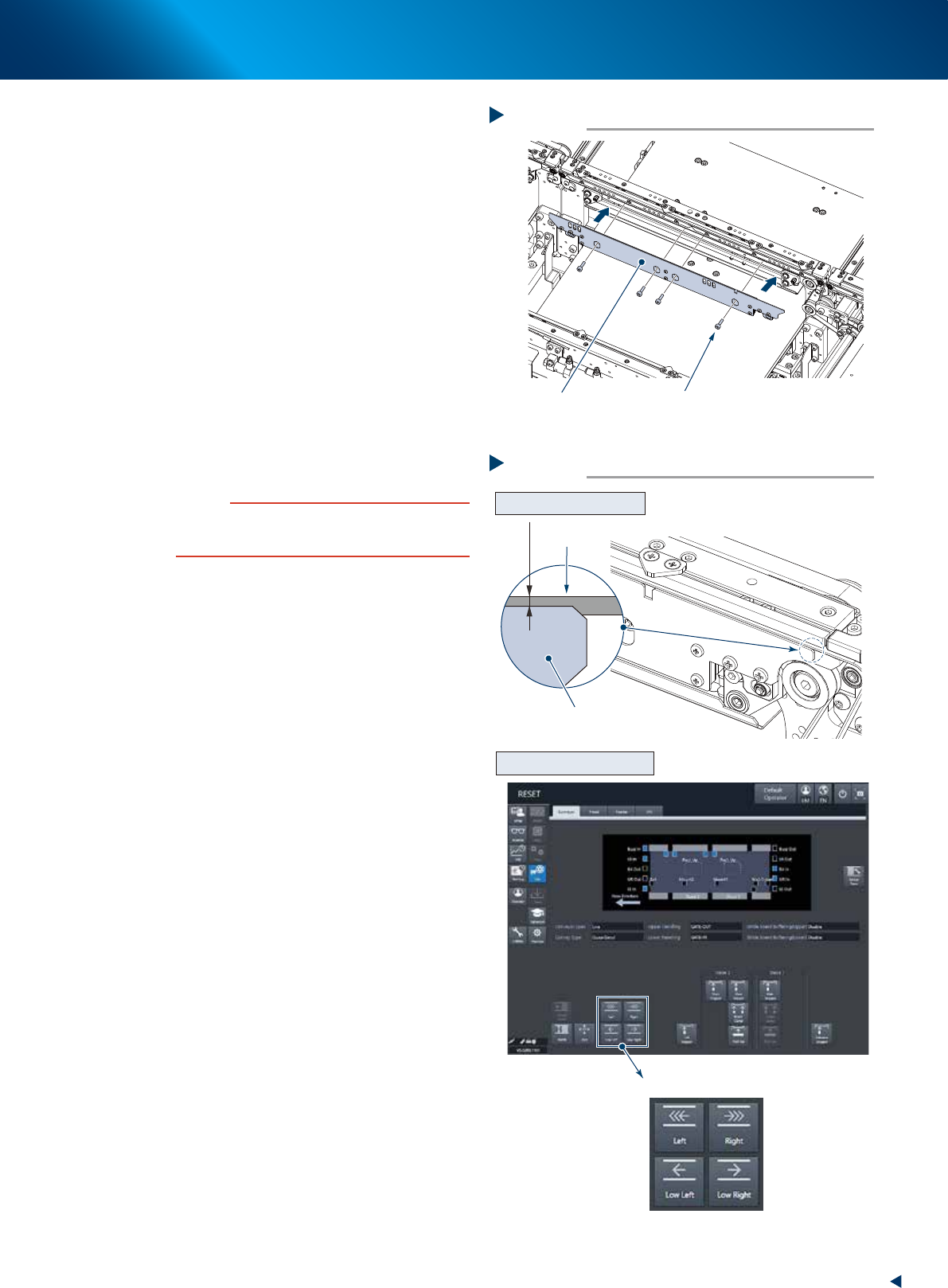
Attach the board clamp plate.
1. Attach the board clamp to its original
position. Mount it by tightening the bolts
using a hexagon wrench (3).
2. Retrieve a square cloth.
0
Check that the conveyor belt is attached
correctly.
1. Check that the upper surface of board clamp
is in a position at approx. 0.5mm lower
than that of the belt.
2. Attach the upper cover, close the machine
safety cover, and attach the feeder
exchange carriage. THen release the
emergency stop.
3. Press the [Conveyor drive] button on the
[Unit] - [Conveyor] screen to run the
conveyor belt and check its motion.
4. When the conveyor belt does not run evenly
or there is a slack in the belt, adjust again
the position of the pulley (for CV2, bracket).
c
CAUTION
When the upper surfaces of belt and board clamp are
almost even, the board transfer error may occur. Contact
your sales representative as such occasion.
Attaching the board clamp plate
Step 9
Board clamp plate 4 mounting bolts
53538-KMX-00
Checking the attached conveyor belt
Step 10
[Conveyor drive] button
Checking the attached status
Checking the conveyor motion
0.5 mm
Board clamp plate
Belt
54503-KMX-00
4. Conveyor unit
5-14
Chapter 5 How to replace consumable parts
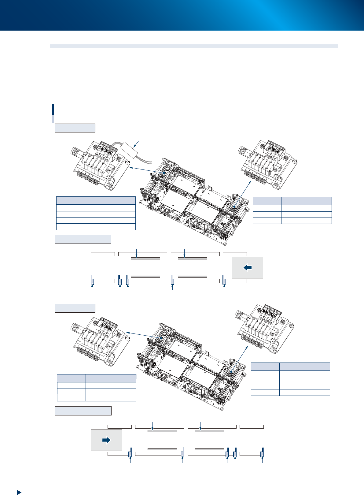
4.2 Replacing the valves at conveyor section
The position and number of valves driving the stopper or board clamp at the conveyor section vary
according to the machine specification or the board transfer direction.
Confirm the valve to be replaced by referring the figure below and the mark tubes attached to the valve
connector cables.
The valve assembly is located at left and right side (conveyor entrance/exit) of conveyor.
CV ST4
CV ST4
CV ST5
CV ST6
CLAMP2
Main stopper 2-1
Main stopper 2-2
Exit stopper
Clamp plate of stage 2
Mark tube
Mark tube
CV ST1
CV ST2
CV ST3
CLAMP1
Exit stopper
Main stopper
2-2
Main stopper 2-1
Clamp plate of stage 1
Mark tube
Valve
Exit stopper
Sub stopper
Main stopper 2-2
Stage 2
Clamp plate 2 Clamp plate 1
Stage 1
Main stopper 2-1 Main stopper 1
CV ST2
CV ST3
CLAMP1
Sub stopper
Main stopper
1
Clamp plate of stage 1
Mark tube Valve
Valve
CV ST4
CV ST6
CLAMP2
Sub stopper
Main stopper
1
Clamp plate of stage 2
Mark tube Valve
Exit stopper
Sub stopper
Main stopper
2-2
Stage 2
Clamp plate 2 Clamp plate 1
Stage 1
Main stopper 2-1
Main stopper 1
Valve position of conveyor section
R to L
L to R
Arrangement of unit
Arrangement of unit
Valve assembly
Valve assembly
Transfer direction
(R to L)
Transfer direction
(L to R)
53531-KMX-00