YRM20_Mainte_E.pdf - 第6页
2. W arning labels iii Safety instructions 2.1.2 Mark description T he mark of warning label includes following 3 types. Eac h mark has its own meaning and is typically used with a pictogram to emphasize the message. WAR…
2. Warning labels
ii
Safety instructions
2. Warning labels
Warning labels are attached to the machine body and peripheral equipment to use YAMAHA
machines safely and correctly. Check that the information on each warning label is clearly legible
and comply with the instructions.
2.1 Warning label format and mark description
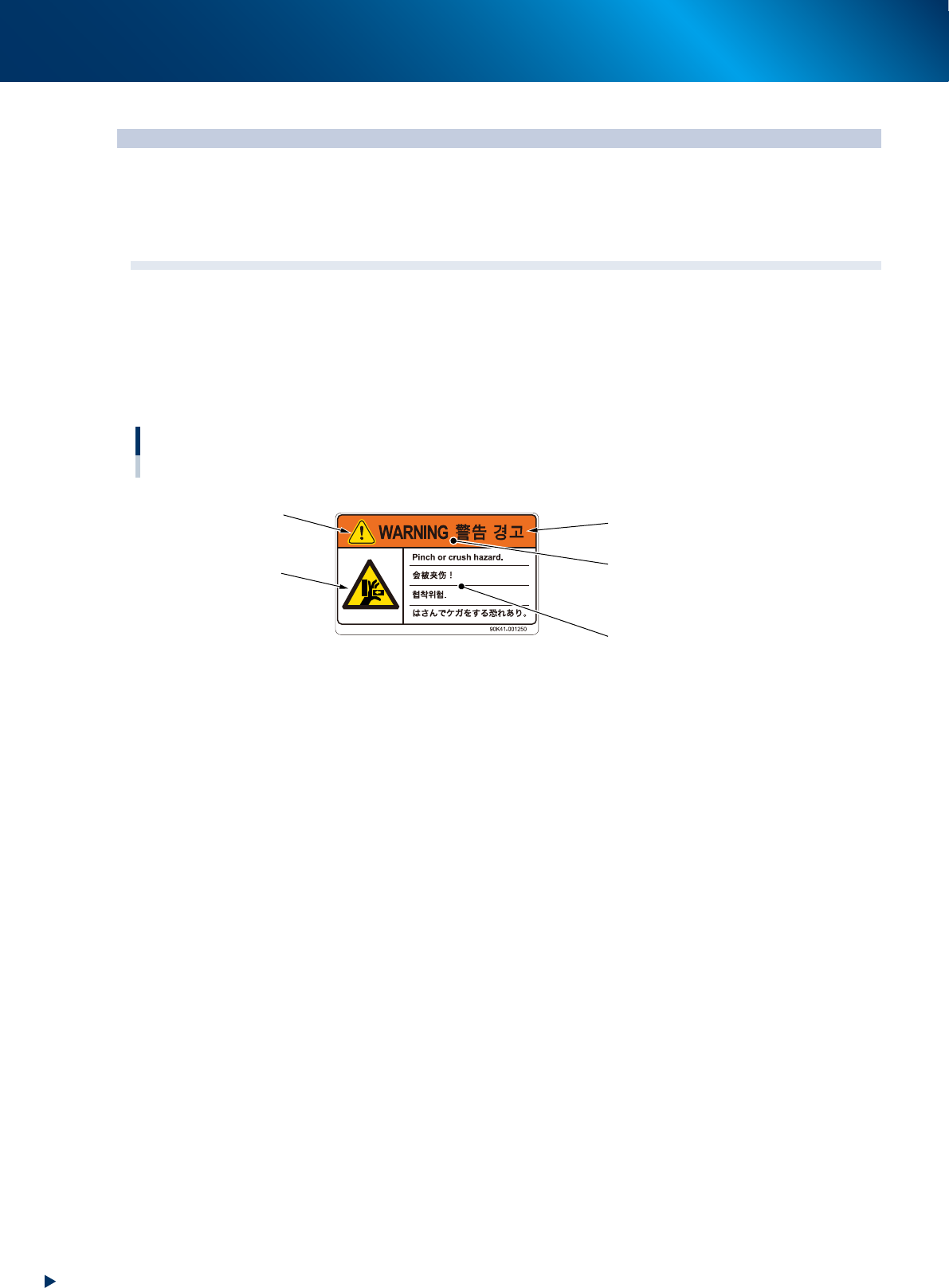
2.1.1 Warning label format
A warning label indicates the degree of hazard by means of a signal word and the color of the signal word
panel as shown below. A mark and a pictogram are also used to emphasize the message.
Labels attached to the outside of machines are basically in 4 languages (English, Chinese, Korean, and
Japanese) while labels attached to the inside of the machines are only a pictogram.
Warning label format
Warning message and mark (pictogram) example
Signal word
Safety alert symbol
Signal word panel
Message
Mark and pictogram
Danger : Red
Warning : Orange
Caution : Yellow
93001-YRM-00
2. Warning labels
iii
Safety instructions
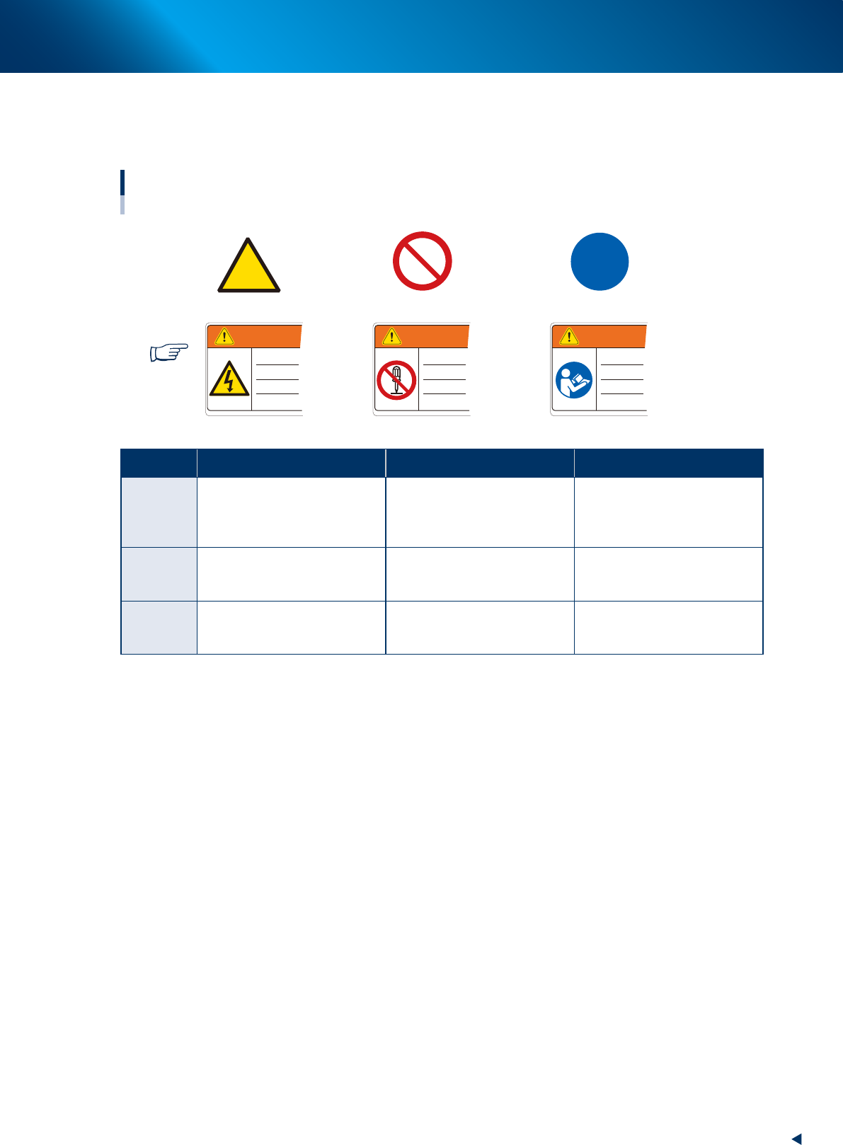
2.1.2 Mark description
The mark of warning label includes following 3 types. Each mark has its own meaning and is typically used
with a pictogram to emphasize the message.
WARNING WARNINGWARNING
Mark and pictogram
Marks and examples used with pictogram
Warning mark Prohibition mark Instruction mark
Usage examples
93002-YRM-00
Warning Prohibition Instruction
Definition
Indicates a hazard, how to
avoid the hazard, and potential
consequences of ignoring the
warning.
Indicates a prohibited action to
avoid the potential hazard.
Indicated an action that must
be taken to avoid the potential
hazard.
Shape/
Color
Yellow triangle with black
border. Pictogram is black on
yellow.
Red circle with slash.
Pictogram is black and located
behind slash.
Blue circle. Pictogram is white
on blue.
Message
example
Risk of electrical shock
Do not modify or disassemble
safety cover switch.
Read the manual to understand
procedure before starting
operation.
3. Label positions
iv
Safety instructions
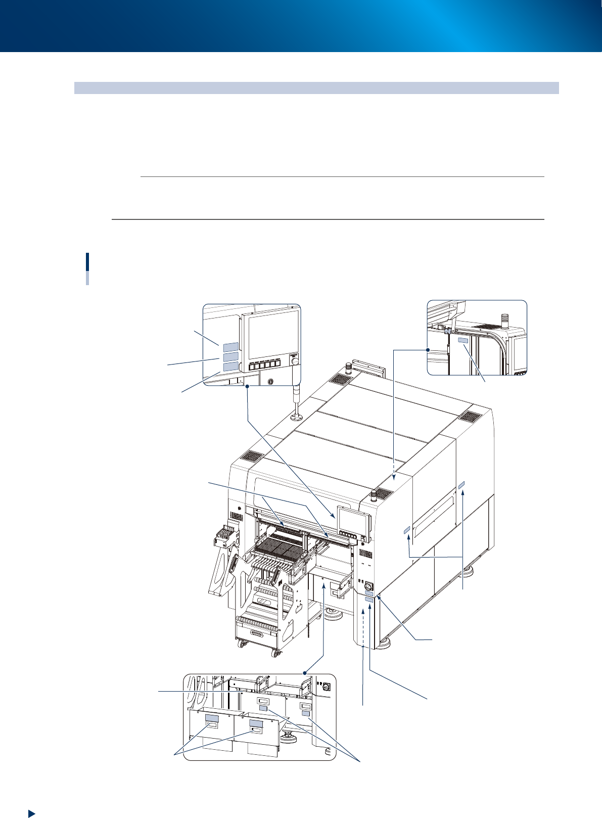
3. Label positions
The following warning/caution labels are attached to YAMAHA products to ensure safe and correct
use. Check that the information on each label is clearly legible and comply with the instructions.
For safety precautions other than those on the labels shown in this section, see the instructions in
"4. Safety".
n
NOTE
• Labels are basically attached to the positions as below, although they may differ slightly depending on specifications, etc.
• See "Power connection terminals" described in the appendix of the maintenance manual when connecting power to this
equipment.
█
Label positions
tooltip
■ Safety cover (front)
No.3
[CAUTION]
Feeder reinsertion
No.4 [WARNING]
Strong magnetic field
No.5 [WARNING]
Injuring hands
No.1 [WARNING]
Precaution for operation
No.2 [WARNING]
Electrical shock hazard
No.5 [WARNING]
Injuring hands
■ Main switch
No.6 [WARNING]
Tampers prohibited
■ Cover inner side
No.2 [WARNING]
Electrical shock hazard
No.7 [WARNING]
Cut hazard
No.8 [CAUTION ]
Crush
No.6 [WARNING]
Tampers prohibited
No.9 [CAUTION ]
Electrical shock hazard
Warning/caution labels
Front
■ Conveyor opening
(right side)
■ Upper cover
■ Power connecting
■ Cover (power connecting)
■ Cutter safety cover (front)
93011-KMX-00