YRM20_Mainte_E.pdf - 第56页
Before maintenance work 2-5 Chapter 2 Daily maintenance items █ T emporary placing of upper cover and precautions The upper cover can be placed temporarily upon handles of feeder exchange carriage. Also, a cover identifi…
Before maintenance work
2-4
Chapter 2 Daily maintenance items
█
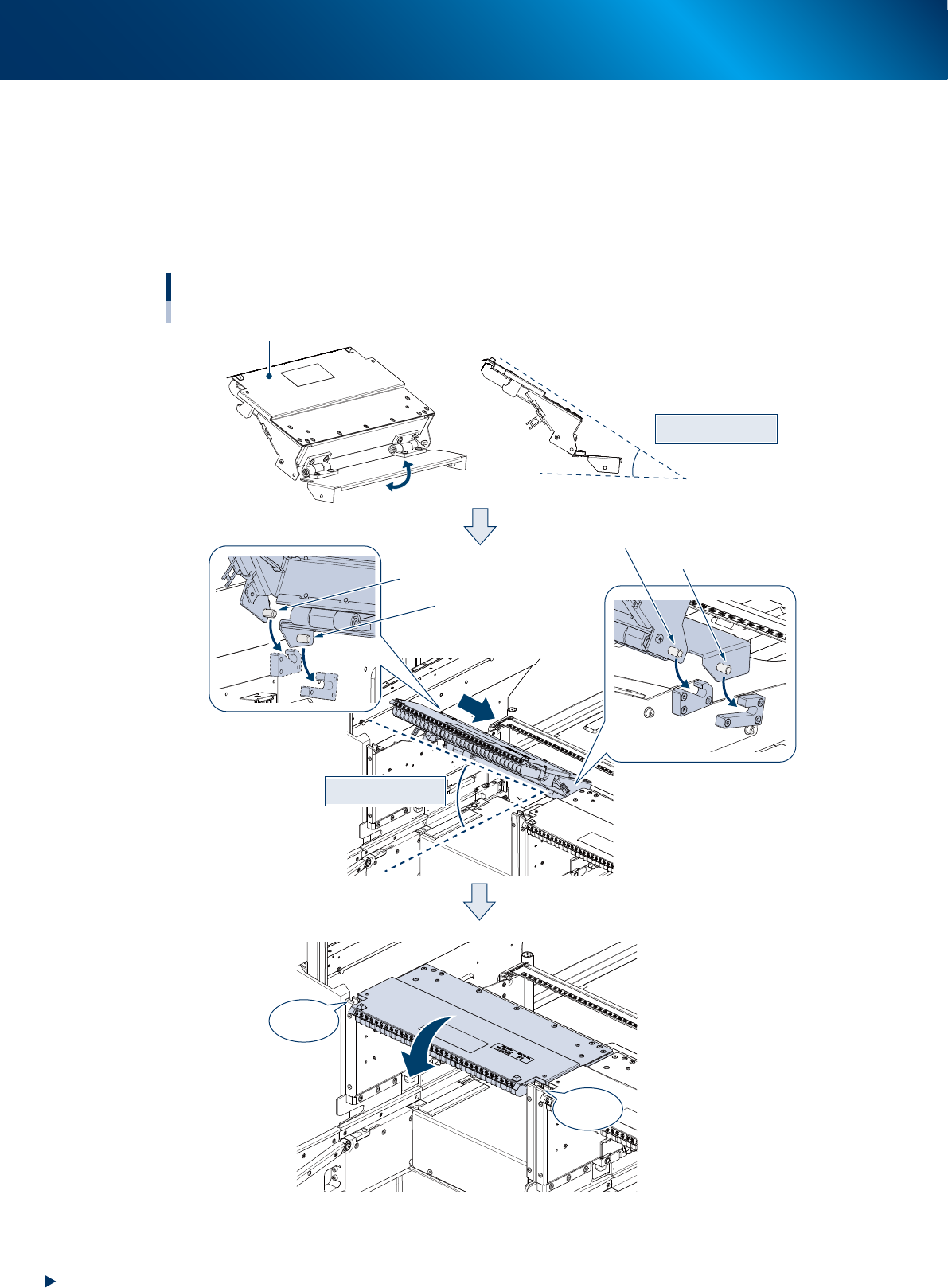
Attaching upper cover
1. Open upper cover end plate manually and hold position of upper cover guide section and end plate
as illustrated below (angle 30 degrees).
2. Insert upper cover into machine at an angle of 30 degrees. At this time, make far end pins and
second far end pins, located at both sides of upper cover, fit into their guides.
3. Close upper cover and confirm the cover locks at both sides click.
Approx. 30 degs.
Attaching upper cover
Approx. 30 degs.
■ Side view
Upper cover guide section
CLICK !
CLICK !
Second far end pin (left)
Far end pin (right)
Second far end pin (right)
Far end pin (left)
Upper cover end plate
53209-KMX-00
Before maintenance work
2-5
Chapter 2 Daily maintenance items
█
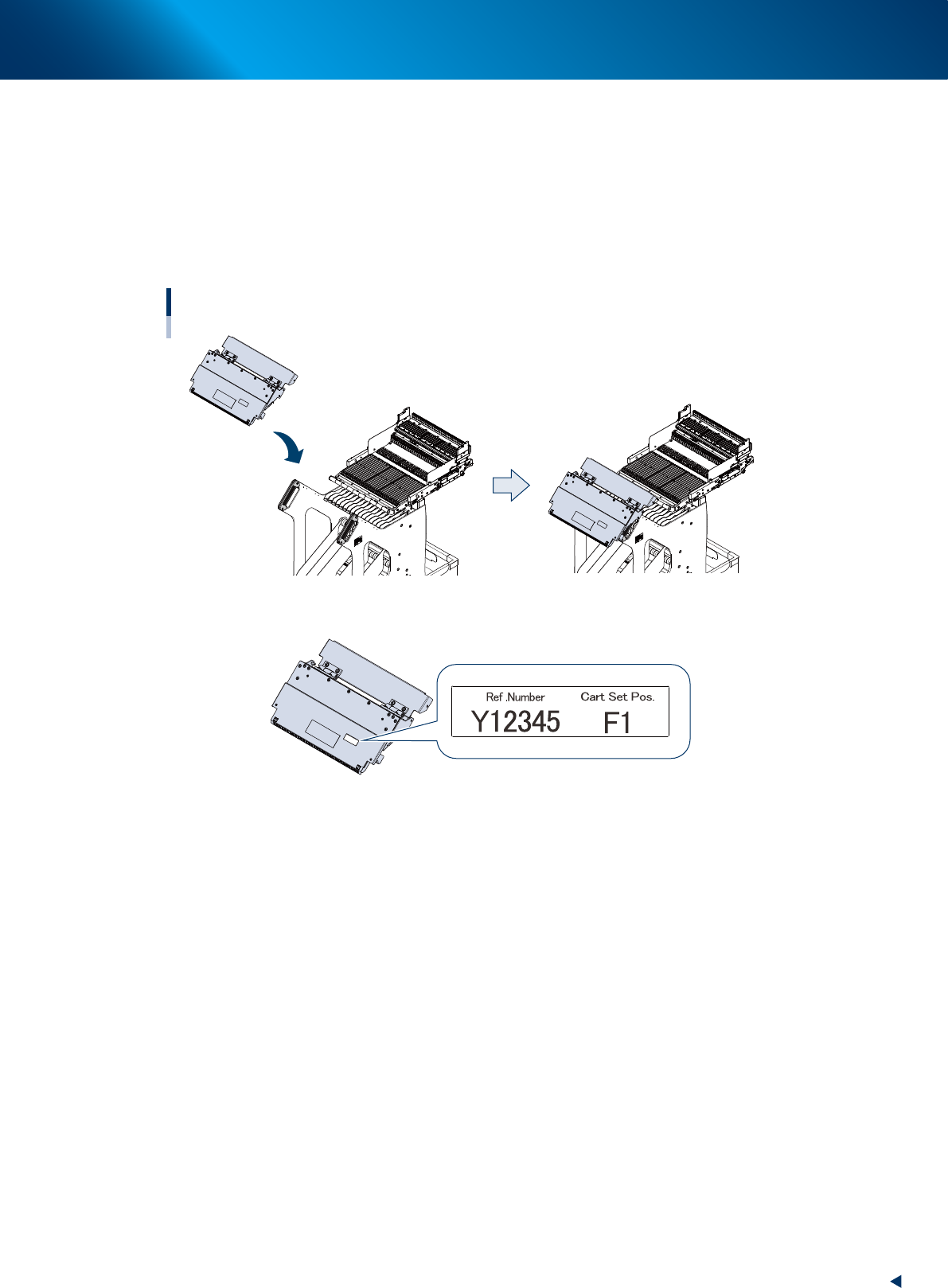
Temporary placing of upper cover and precautions
The upper cover can be placed temporarily upon handles of feeder exchange carriage.
Also, a cover identification label attached to upper cover carries machine serial number and number of
carriage set position.
The upper cover is not compatible for other carriage set position or other machine, as the guide position
is adjusted for the correspond machine upon assembling and then the carriage is shipped. Use with the
machine/carriage set position written on cover identification label.
Temporary placing of upper cover
■ Cover identification label
53210-KMX-00
1. Checking the nozzle
2-6
Chapter 2 Daily maintenance items
1. Checking the nozzle
Solder sticking to the nozzle tip or a clogged nozzle hole can cause component pickup error and
recognition error. Moreover, poor spring action of nozzles may cause pickup errors. Inspect each nozzle
on a daily basis to prevent the errors.
1.1 Checking with software
█
How to check for a dirty nozzle (with the [Nozzle Cln Check] button)
The term "Nozzle Clean" as used here indicates shiny material such as solder adhering to the nozzle tip.
This shiny portion might be mistaken for a component and cause recognition errors. [Nozzle Cln Check] is a
tool that judges the nozzle contamination status by recognizing the nozzle tip in the non-component status
with the camera.
n
NOTE
The [Nozzle Cln Check] is a function that recognizes the
reflection of the light around the nozzle center. Therefore,
applicable nozzles are those with a small tip, such as
Type 8104A and 8105A.
1
(When the nozzle station is not
equipped) Replace the nozzle.
1. Press the [Required Nozzles] button on the
"Setup" screen to check the nozzles to be
used for production.
e
2. Press the emergency stop button and then
open the machine safety cover.
3. Attach nozzles to be used for production to
head.
4. Close the machine safety cover and then
cancel the emergency stop.
n
NOTE
Step 1 can be skipped if the machine is equipped with
the nozzle station.
2
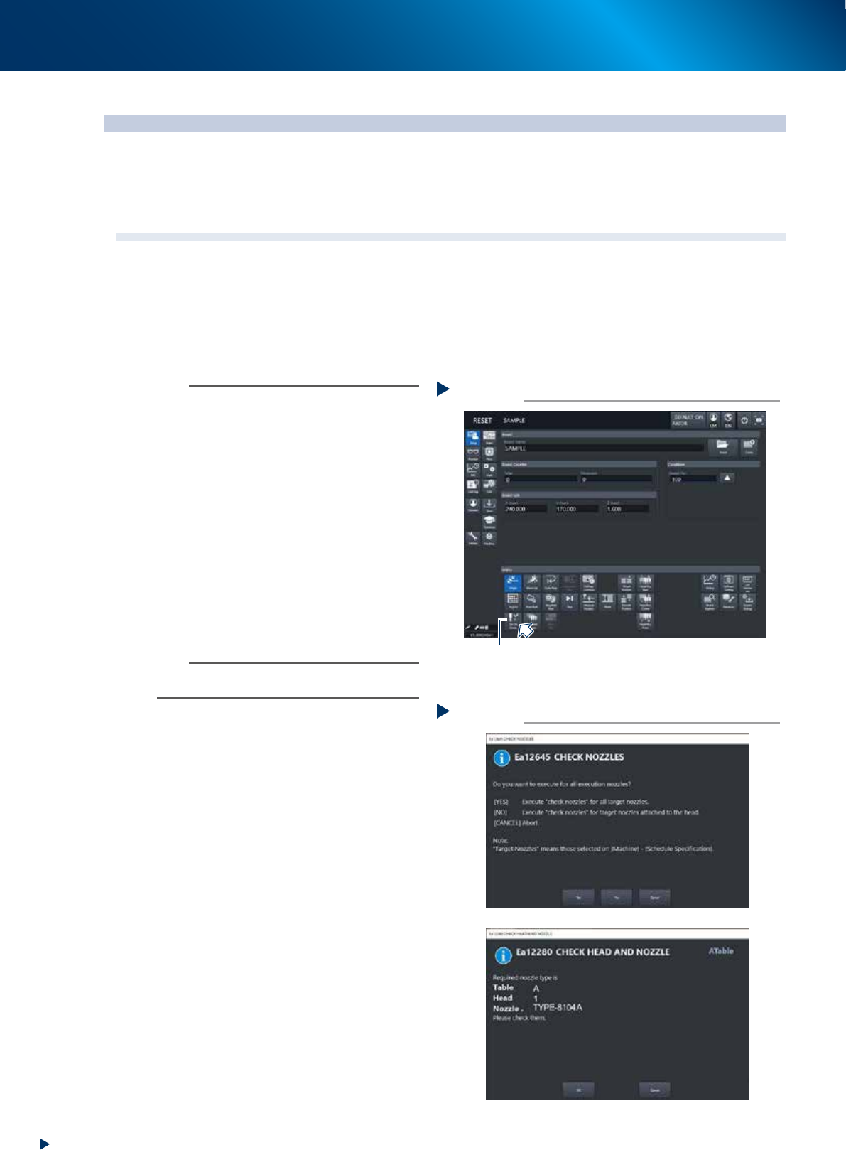
Press the [Nozzle Cln Check] button on
the "Setup" screen.
3
Select item to be executed.
After checking the displayed message, select
the desired button.
►
When selected [Yes]
Performs auto nozzle change and checks all
relevant nozzles.
►
When selected [No]
Checks relevant nozzles of all nozzles currently
attached to the head.
4
Check the message.
If the result is Not OK, clean the nozzle
referring to "1.2 Nozzle cleaning"" in Chapter
3.
Selecting item to be executed
Step 3
When [No] was selected
54201-KMX-00
Press the [Nozzle Cln Check] button
Step 2
[Nozzle Cln Check] button
54200-KMX-00