YRM20_Mainte_E.pdf - 第164页
4. Conveyor unit 5-15 Chapter 5 How to replace consumable parts █ V alve replacement procedur e 1 e 1Pr e pare for work . 1. Press t he emergency stop button and detach the carriage. 2. Exit the software and power off th…
4. Conveyor unit
5-14
Chapter 5 How to replace consumable parts
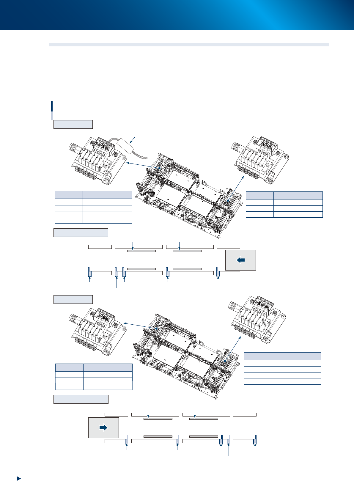
4.2 Replacing the valves at conveyor section
The position and number of valves driving the stopper or board clamp at the conveyor section vary
according to the machine specification or the board transfer direction.
Confirm the valve to be replaced by referring the figure below and the mark tubes attached to the valve
connector cables.
The valve assembly is located at left and right side (conveyor entrance/exit) of conveyor.
CV ST4
CV ST4
CV ST5
CV ST6
CLAMP2
Main stopper 2-1
Main stopper 2-2
Exit stopper
Clamp plate of stage 2
Mark tube
Mark tube
CV ST1
CV ST2
CV ST3
CLAMP1
Exit stopper
Main stopper
2-2
Main stopper 2-1
Clamp plate of stage 1
Mark tube
Valve
Exit stopper
Sub stopper
Main stopper 2-2
Stage 2
Clamp plate 2 Clamp plate 1
Stage 1
Main stopper 2-1 Main stopper 1
CV ST2
CV ST3
CLAMP1
Sub stopper
Main stopper
1
Clamp plate of stage 1
Mark tube Valve
Valve
CV ST4
CV ST6
CLAMP2
Sub stopper
Main stopper
1
Clamp plate of stage 2
Mark tube Valve
Exit stopper
Sub stopper
Main stopper
2-2
Stage 2
Clamp plate 2 Clamp plate 1
Stage 1
Main stopper 2-1
Main stopper 1
Valve position of conveyor section
R to L
L to R
Arrangement of unit
Arrangement of unit
Valve assembly
Valve assembly
Transfer direction
(R to L)
Transfer direction
(L to R)
53531-KMX-00
4. Conveyor unit
5-15
Chapter 5 How to replace consumable parts
█
Valve replacement procedure
1
e
1Prepare for work.
1. Press the emergency stop button and detach
the carriage.
2. Exit the software and power off the machine.
3. Turn the air supply/exhaust switch on the
lower left of the machine clockwise (EXT).
4. Open the machine safety cover and detach
off the upper cover.
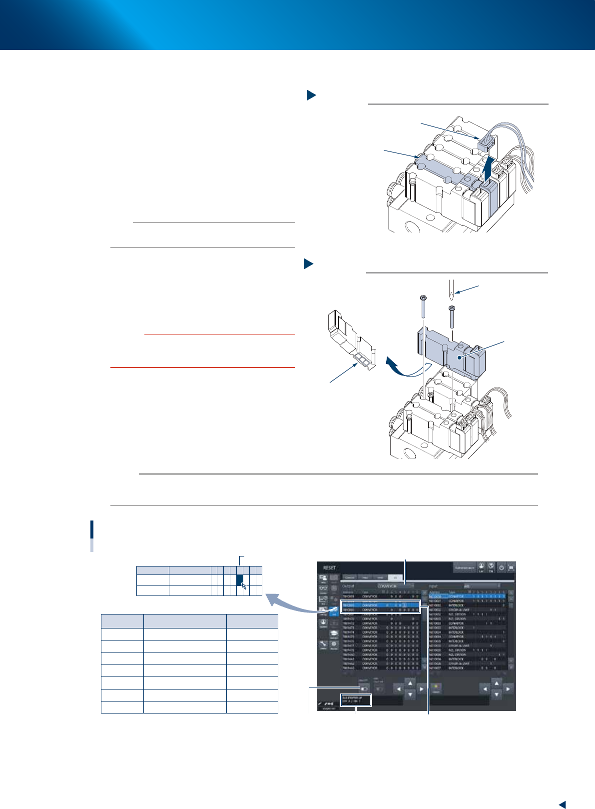
2
Detach the connector to be replaced.
n
NOTE
Confirm the valve to be replaced by checking the mark
tube attached to the connector cable.
3
Replace the valve.
1. Remove 2 mounting screws of the target
valve using Phillips precision screwdriver.
2. Attach a new valve.
3. Connect the connector.
c
CAUTION
The packing is attached to the back of the valve.
Replace the valve with a new one while carefully checking
the packing for dropping or catching.
4
Check the valve operation.
1. Attach the upper cover and close the
machine safety cover.
2. Turn on the air supply and machine power,
and attach the feeder exchange carriage.
3. Check the replaced valve operation at [Unit]
- [I/O] screen.
n
NOTE
The example shown below is of R to L flow direction.
Confirm the actual address and operate after replacing the valve.
Mark tube Address
Sub stopper
Main stopper 1
Main stopper 2-1
Main stopper 2-2
Exit stopper
Clamp plate of stage 1
Clamp plate of stage 2
Description
T010005
T010005
T010006
T010006
T010006
T010005
T010006
-
-
-
-
-
-
-
3
4
1
2
3
5
4
Example: T010005 - 3
CV ST2
CV ST3
CV ST4
CV ST5
CV ST6
CLAMP1
CLAMP2
Address
T010005
T010006
Type
CONVEYOR
CONVEYOR
7
0
6
0
5
0
4
0
0
3
0
0
2
0
1
0
0
0
0
Checking the conveyor valve operation
Example: R to L
Select the "CONVEYOR" of Output side
Select address[ON/OFF] button Detail of address
54504-KMX-10
Step 2
Detaching the valve connector
Connector
Valve to be replaced
53533-KMX-10
Step 3
Valve replacement
Phillips precision
screwdriver
Valve
Be careful not to drop off
the packing installed at
the reverse side of valve
53534-KMX-10
5. Base
5-16
Chapter 5 How to replace consumable parts
5. Base
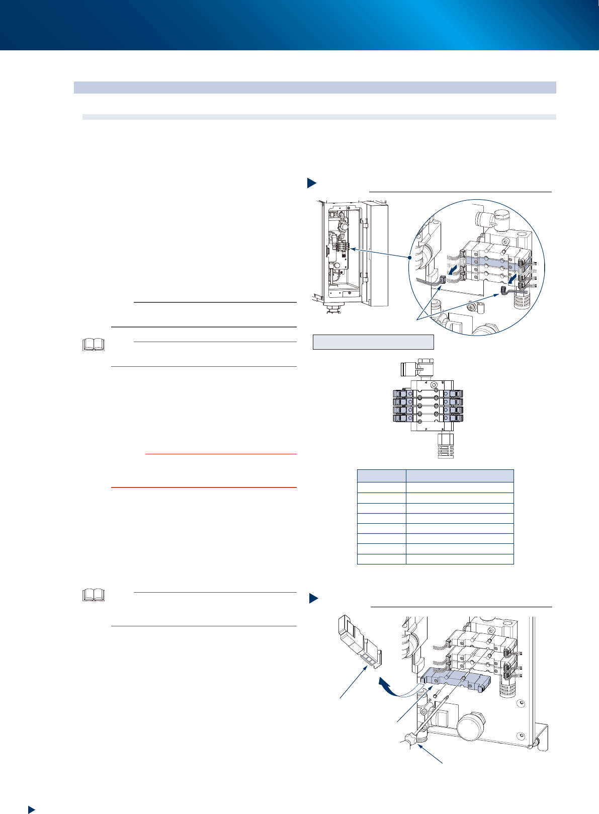
5.1 Replacing carriage clamp valve
The clamp valve for feeder exchange carriage locates on the bottom left of machine front. When the valve
has a problem, replace it with the following procedure.
1
Turn off the main power and air supply
of the machine.
1. Close the applications and turn the machine
off.
2. Turn the air supply/exhaust switch clockwise
(EXH) to turn off the air supply.
2
Disconnect the connector of the target
valve.
n
NOTE
See the figure right, and marked tube attached to the
valve connector for the target valve and its position.
TIP
The double solenoid valve controls the clamp/unclamp of
carriage.
3
Replace the valve.
1. Remove bolts (2 each) mounting target valve
with Phillips precision screwdriver.
2. Attach a new valve.
3. Connect the connector.
c
CAUTION
The packing is attached to the back of the valve. Replace
the valve with a new one while carefully checking the
packing for dropping or catching.
4
Check the valve operation.
1. Turn on the air supply and main power
supply.
2. Confirm by clamping/unclamping the
carriage in real to confirm that the carriage
can be set correctly after the carriage clamp
or unclamp valve was replaced.
TIP
The carriage clamp valve operation can be also checked
on [Unit] - [I/O] screen. See "Valve operation check on the
"I/O" screen" below.
Step 2
R2 DownR2 UP
F1 UP
F2 UP
R1 UP
F1 Down
F2 Down
R1 Down
F1 Down
F2 Down
R1 Down
R2 Down
F1 UP
F2 UP
R1 UP
R2 UP
Front left
Front right
Rear right
Rear left
Front left
Front right
Rear right
Rear left
: clamp the carriage
: clamp the carriage
: clamp the carriage
: clamp the carriage
: unclamp the carriage
: unclamp the carriage
: unclamp the carriage
: unclamp the carriage
Mark tube Valve
Removing valve connector
Connector
Valve position and its function
53529-KMX-10
Valve replacement
Step 3
Phillips precision driver
Double solenoid valve
The packing is attached.
Be careful of dropping off
53530-KMX-00