99469_UR16e_User_Manual_zh_Global.pdf - 第92页
SF# an d Safety Func ti o n D e s c ri pti on What hap pen s ? Tol e- ranc e PFH d Affec ts SF2 Safegu ard Stop4 (P ro tec tiv e Stop ac c ordi ng to ISO 102 18-1 ) Thi s sa fety func tion is ini tiate d by an ex terna l…
17.安全功能表
17.1. Table 1
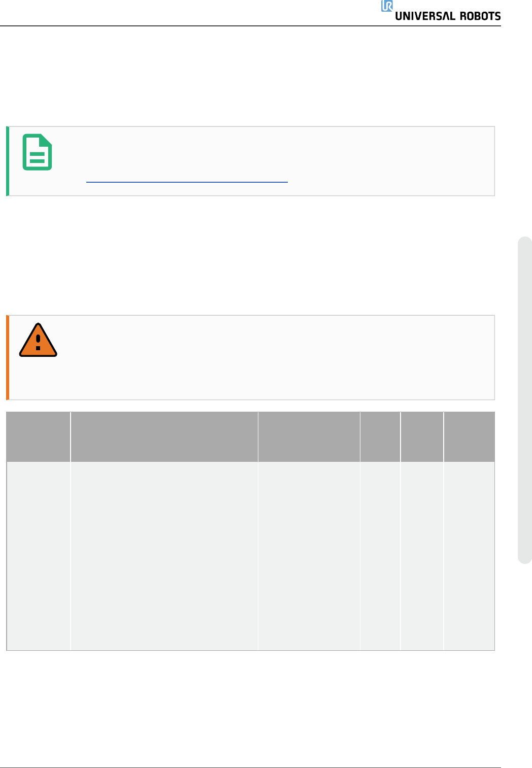
提示
本章中介绍的安全功能表是简化版本。您可以访问以下链接查看其完整版
本:https://www.universal-robots.com/support
Universal Robots e-Series Safety Functions and Safety I/O are PLd, Category 3 (ISO 13849-1), with
certification by TŰV NORD (certificate # 44 207 14097610).
Safety Function (SF) Descriptions (see Chapter 2 of manual: For safety I/O, the resulting safety
function including the external device or equipment is determined by the overall architecture and the
sum of all PFHds, including the UR robot safety function PFHd. All safety functions are individual safety
functions.
警告
If any safety function limit is exceeded, or a fault is detected in a safety function or
safety-related part of the control system, the result is a Category 0 stop (immediate
removal of power) according to IEC 60204-1.
SF# and
Safety
Function
Description What happens?
Tole-
rance
PFHd Affects
SF1
1,2,3,4
Emergency
Stop
(according
to ISO
13850)
Pressing the Estop PB on the
pendant1 or the External Estop (if
using the Estop Safety Input) results
in a Cat 1 stop with power removed
from the robot actuators and the tool
I/O. Command1 all joints to stop and
upon all joints coming to a monitored
standstill state, power is removed.
See Stop Time and Stop Distance
Safety Functions. ONLY USE FOR
EMERGENCY PURPOSES, not
safeguarding.
Category 1 stop
(IEC 60204-1)
-
1.30E-
07
Robot
including
robot
tool I/O
用 户 手 册 77 UR16e
17.安 全功 能表
版 权所 有 © 2009–2021UniversalRobotsA/S。保留 所 有 权利。
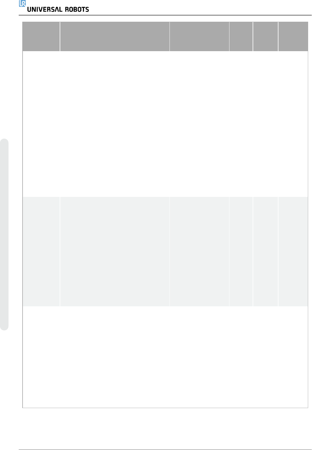
SF# and
Safety
Function
Description What happens?
Tole-
rance
PFHd Affects
SF2
Safeguard
Stop4
(Protective
Stop
according
to ISO
10218-1)
This safety function is initiated by an
external protective device using
safety inputs which will initiate a Cat 2
stop3. The tool I/O are unaffected by
the safeguard stop. Various
configurations are provided. If an
enabling device is connected, it is
possible to configure the safeguard
stop to function in automatic mode
ONLY. See the Stop Time and Stop
Distance Safety Functions4 . For the
functional safety of the complete
integrated safety function, add the
PFHd of the external protective
device to the PFHd of the Safeguard
Stop.
Category 2 stop
(IEC 60204-1) SS2
stop (as described
in IEC 61800-5-2)
-
1.20E-
07
Robot
SF3
Joint
Position
Limit (soft
axis
limiting)
Sets upper and lower limits for the
allowed joint positions. Stopping time
and distance is not a considered as
the limit(s) will not be violated. Each
joint can have its own limits. Directly
limits the set of allowed joint positions
that the joints can move within. It is
set in the safety part of the User
Interface. It is a means of safety-rated
soft axis limiting and space limiting,
according to ISO 10218-1:2011,
5.12.3.
Will not allow
motion to exceed
any limit settings.
Speed could be
reduced so motion
will not exceed any
limit. A protective
stop will be initiated
to prevent
exceeding any limit.
5°
1.20E-
07
Joint
(each)
SF4
Joint
Speed
Limit
Sets an upper limit for the joint speed.
Each joint can have its own limit. This
safety function has the most influence
on energy transfer upon contact
(clamping or transient). Directly limits
the set of allowed joint speeds which
the joints are allowed to perform. It is
set in the safety setup part of the User
Interface. Used to limit fast joint
movements, e.g. risks related to
singularities.
Will not allow
motion to exceed
any limit settings.
Speed could be
reduced so motion
will not exceed any
limit. A protective
stop will be initiated
to prevent
exceeding any limit.
1.15
°/s
1.20E-
07
Joint
(each)
UR16e 78 用 户 手 册
17.安 全功 能表
版 权所 有 © 2009–2021UniversalRobotsA/S。保留 所 有 权利。

SF# and
Safety
Function
Description What happens?
Tole-
rance
PFHd Affects
Joint
Torque
Limit
Exceeding the internal joint torque
limit (each joint) results in a Cat 0
stop3. This is shown as SF #5 in the
Generation 3 (CB3) UR robots. This
is not accessible to the user; it is a
factory setting. It is NOT shown as a
safety function because there are no
user settings and no user
configuration possibilities.
- - - -
SF5
Called
various
names:
Pose Limit,
Tool Limit,
Orientation
Limit,
Safety
Planes,
Safety
Boundaries
Monitors the TCP Pose (position and
orientation) and will prevent
exceeding a safety plane or TCP
Pose Limit. Multiple pose limits are
possible (tool flange, elbow, and up to
2 configurable tool offset points with a
radius) Orientation restricted by the
deviation from the feature Z direction
of the tool flange OR the TCP. This
safety function consists of two parts.
One is the safety planes for limiting
the possible TCP positions. The
second is the TCP orientation limit,
which is entered as an allowed
direction and a tolerance. This
provides TCP and wrist inclusion/
exclusion zones due to the safety
planes.
Will not allow
motion to exceed
any limit settings.
Speed or torques
could be reduced
so motion will not
exceed any limit. A
protective stop will
be initiated to
prevent exceeding
any limit. Will not
allow motion to
exceed any limit
settings.
3 °
40
mm
1.20E-
07
TCP
Tool
flange
Elbow
SF6
Speed
Limit TCP
& Elbow
Monitors the TCP and elbow speed
to prevent exceeding a speed limit.
50
mm/s
1.20E-
07
TCP
用 户 手 册 79 UR16e
17.安 全功 能表
版 权所 有 © 2009–2021UniversalRobotsA/S。保留 所 有 权利。