Printer 710-810 v9 ProFlow ATX.pdf
PROFLOW ATX OVERVIEW Chapter Issue 6, Jan 16 Technical Reference Manual 12.1 CHAPTER 12 PROFLOW A TX OVER VIEW Figure 12-1 ProFlow A Tx System Component s The ProFlow® A Tx system attaches to the print carriage and is us…
PROFLOW ATX
OVERVIEW
Chapter Issue 6, Jan 16 Technical Reference Manual 12.1
CHAPTER 12 PROFLOW ATX
OVERVIEW
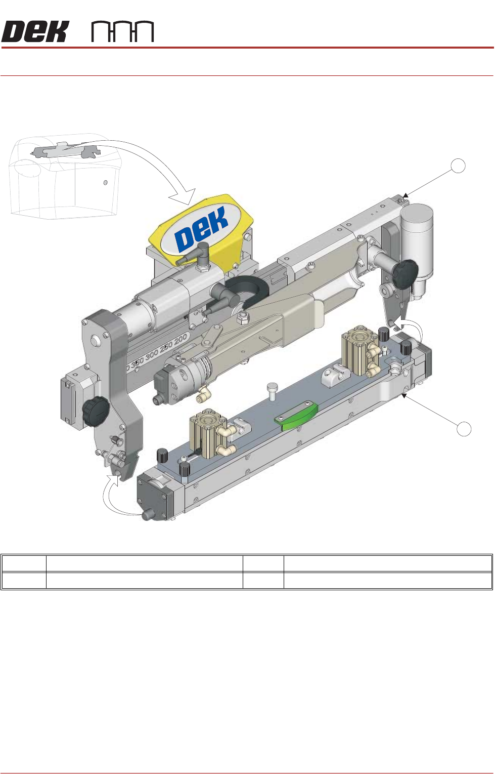
Figure 12-1 ProFlow ATx System Components
The ProFlow® ATx system attaches to the print carriage and is used to print
various high viscosity materials which display non-Newtonian characteristics.
The system can accommodate two different sized cartridges of print medium
(6 fl oz and 12 fl oz) which is delivered to the transfer head by pneumatic
pressure.
As the print carriage drives the system across the stencil, the constant system
pressure and the enclosed design of the transfer head ensures minimum
wastage and maximum environmental protection of the print medium.
The detachable transfer head is available in 300mm or 400mm configurations;
this provides effective coverage for different sized substrates, as well as optimal
print medium application.
Item Description Item Description
1 System Mount 2 Transfer Head Unit
2
1
PROFLOW ATX
OVERVIEW
12.2 Technical Reference Manual Chapter Issue 6, Jan 16
System Mount
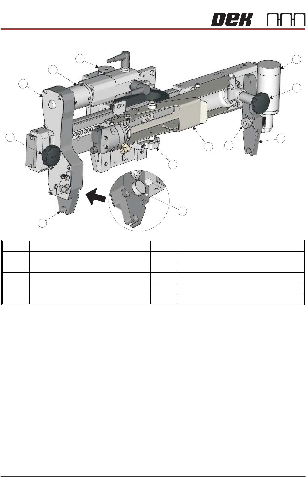
The system mount has two adjustable transfer head mount brackets and a
transfer head pin mount to support the transfer head.
The left mount bracket contains the drive system for the conditioning grid and
the right mount bracket has the drive system for the Archimedes screw, incor-
porated in the transfer head mechanism.
A Z-axis stepper motor drives the ProFlow system up and down, delivering the
transfer head to the print contact height and applying system pressure.
Item Description Item Description
1 Archimedes Screw Motor 6 Transfer Head Pin Mount
2 Mount Thumbscrew (2 positions) 7 Conditioning Grid Drive Cog
3 Transfer Head Mount Bracket (2 positions) 8 Conditioning Grid Drive Mechanism
4 Archimedes Screw Drive Cog 9 Conditioning Grid Motor
5 Cartridge Load Mechanism 10 Z-axis Motor (protective cover removed)
3
1
2
6
2
8
9
10
4
5
3
7
PROFLOW ATX
OVERVIEW
Chapter Issue 6, Jan 16 Technical Reference Manual 12.3
Transfer Head
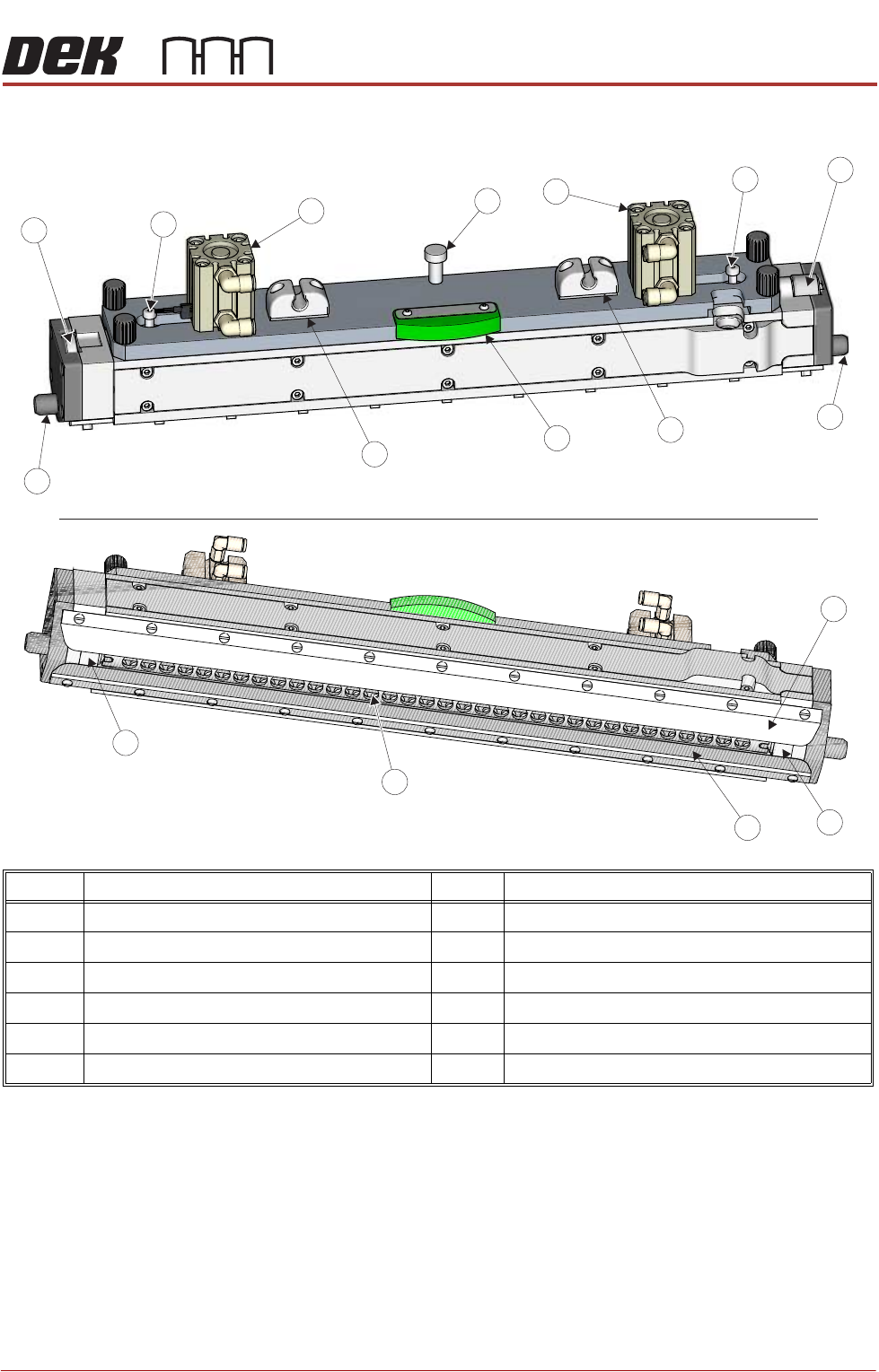
The transfer head is a detachable assembly with a sealed twin chamber
configuration. This protects the print medium from the environment after it has
been pneumatically driven out of the paste cartridge.
An Archimedes screw distributes the print medium along the length of the
conditioning chamber and a crosshead piston pushes down on it, providing a
pressurised environment. This, along with the rotating conditioning grid, pre-
pares the print medium for printing.
As the transfer head moves across the stencil, the print medium is forced
through the apertures in the stencil by a combination of the system pressure,
the print medium pressure, and the rolling action of the conditioning grid.
Item Description Item Description
1 Pin Mount 7 Print Medium Type Indicator
2 Print Medium Pneumatic Cylinder (2 positions) 8 Conditioning Grid Drive Gear
3 Print Medium Level Indicator Pin (2 positions) 9 Front Wiper Blade
4 Archimedes Screw Drive Gear 10 Side Ski (2 positions)
5 Locator Dowel (2 positions) 11 Rear Wiper Blade
6 Base Cover Mount (2 positions) 12 Conditioning Grid
4
3
3
2
1
5
5
11
12
9
10
10
View On Top
View On Underneath
7
6
6
8
2