Printer 710-810 v9 ProFlow ATX.pdf - 第45页
PROFLOW ATX REPLACEMENT PROCEDURES Chapter Issue 6, Jan 16 Technical Reference Manual 12.45 1 1. Remove the two print med ium level indicator pins from the crosshead piston, using a 2.5mm Allen key . 12. Slide the crossh…
PROFLOW ATX
REPLACEMENT PROCEDURES
12.44 Technical Reference Manual Chapter Issue 6, Jan 16
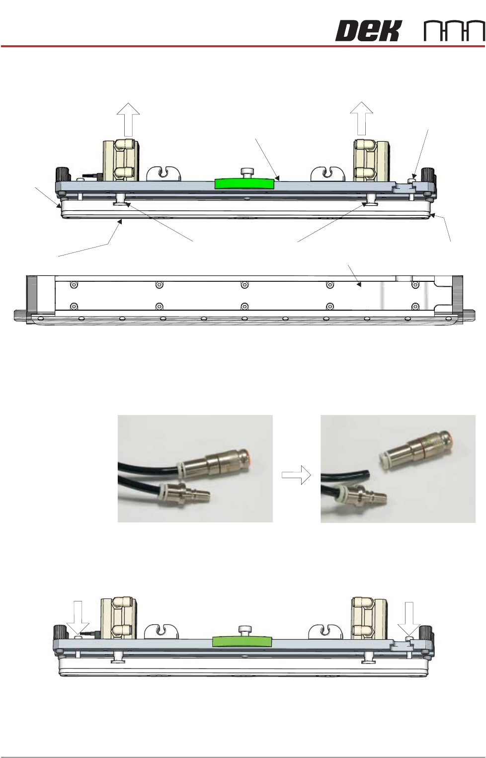
7. Separate the main body of the transfer head from the top plate and cross-
head piston assembly.
8. Remove the pneumatic connector from the crosshead piston’s down air feed
pipe; this allows easy movement of the crosshead piston pneumatic sole-
noids.
9. Push the crosshead piston away from the top plate (into its down position),
using the two print medium level indicator pins.
10. Refit the pneumatic connector onto the piston’s down air feed (to prevent
the piston from retracting back towards the top plate).
Transfer Head Main Body
Crosshead
Piston
Crosshead
Piston Seal
Crosshead Piston Shafts
View on Front of Transfer Head
Piston Seal
Retainer
Print Medium Level
Indicator (2 Positions)
Transfer Head
Top Plate
View on Piston Air Feed Pneumatic Connectors
Connector Attached to Pipe
Connector Disconnected from Pipe
Piston Up
Piston Down
View on Front of Transfer Head
PROFLOW ATX
REPLACEMENT PROCEDURES
Chapter Issue 6, Jan 16 Technical Reference Manual 12.45
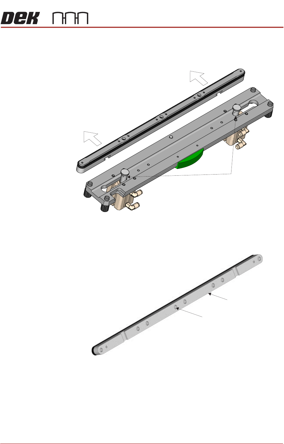
11. Remove the two print medium level indicator pins from the crosshead piston,
using a 2.5mm Allen key.
12. Slide the crosshead piston off the piston shafts.
13. Remove the piston seal retainer securing screws from the crosshead piston,
using a 2.5mm Allen key.
NOTE
The amount of retaining screws vary with transfer head size.
View on Underside of Transfer Head Top Plate
Piston Shafts
View on Top (400mm Transfer Head Piston Shown)
Retainer Securing Screws
(8 positions)
Crosshead Piston
PROFLOW ATX
REPLACEMENT PROCEDURES
12.46 Technical Reference Manual Chapter Issue 6, Jan 16
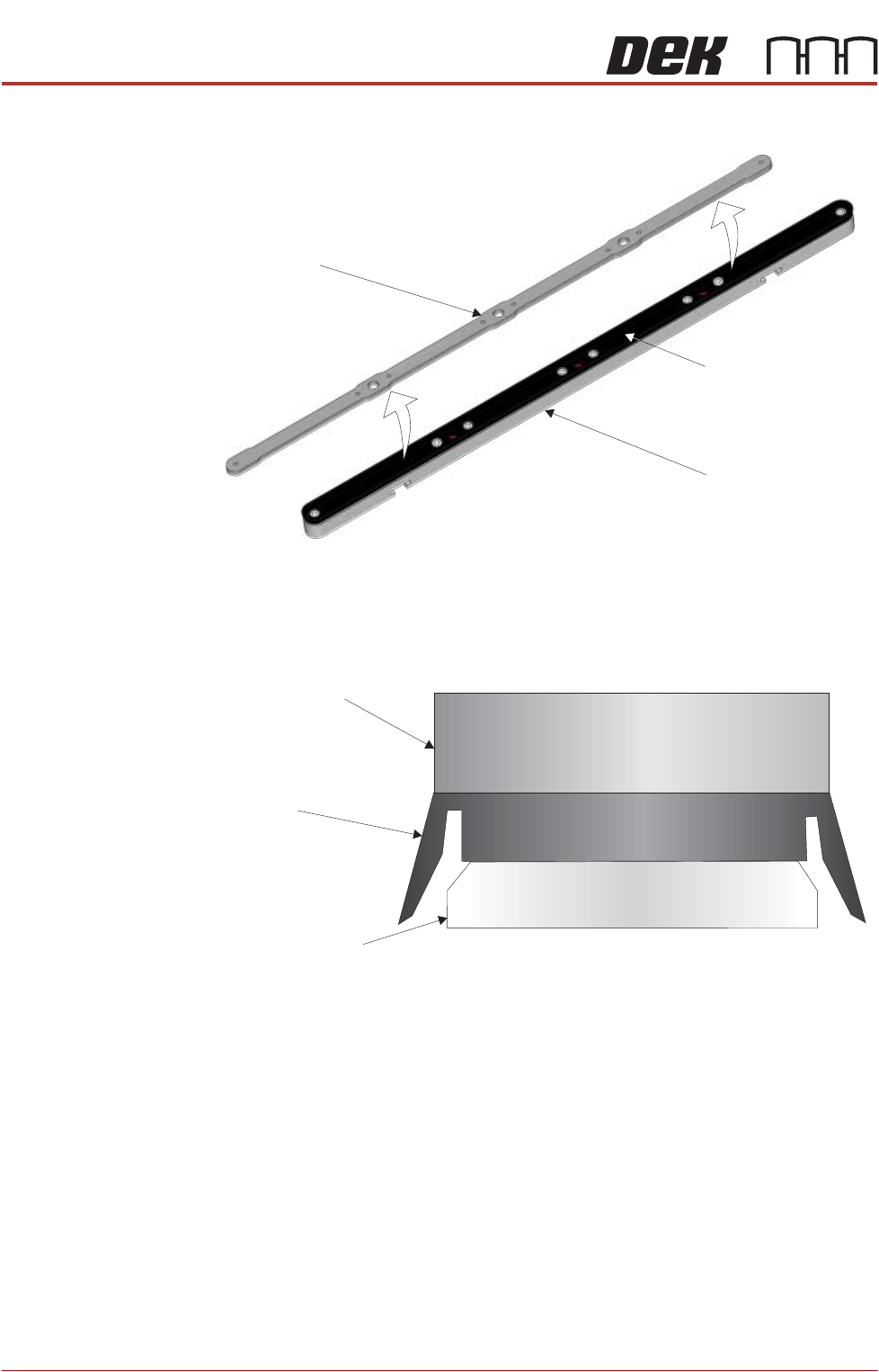
14. Remove the piston seal retainer.
15. Remove the existing piston seal.
16. Fit the new piston seal.
17. Refit the piston seal retainer as shown in the graphic below.
18. Secure the piston seal retainer with the screws removed earlier.
19. Align the flat edges of the crosshead piston shafts to the slots in the
crosshead piston.
20. Fit the crosshead piston to the aligned piston shafts.
21. Fit the print medium level indicator pins (2 positions) to the crosshead piston,
using a 2.5mm Allen key.
22. Fit the top plate to the main body of the transfer head.
23. Tighten the four captive thumbscrews on the transfer head top plate.
View on Bottom of Crosshead Piston
Piston Seal
Retainer
Crosshead Piston
Crosshead
Piston Seal
View on End of Crosshead Piston
Piston Seal Retainer
Piston Seal
Crosshead Piston